10fitting the upper soft stop mechanism, 11aligning the doors, 4insertion into a row of kitchen units – Liebherr CBNPgb 3956 Premium BioFresh NoFrost User Manual
Page 9: Putting into operation, 4 insertion into a row of kitchen units
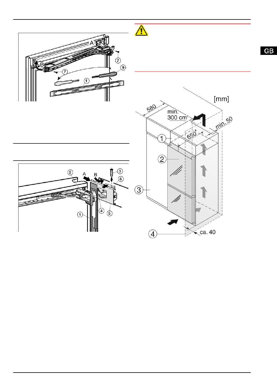
4.3.10 Fitting the upper soft stop mechanism
Fig. 15
u
Remove the cover
Fig. 15 (9)
from the faceplate
Fig. 15 (1)
and re-insert it at the other side.
u
Engage the upper soft stop unit with the joint on the hinge
side (A) and swivel into place (B).
w
The screw holes at the left and right have to register.
u
Screw the soft stop unit firmly into place(2 mal Torx® 15)
Fig. 15 (7)
.
Note
u
Keep to the correct order. First attach the panel over the soft
stop bracket, then the cover.
Fig. 16
u
Attach the faceplate
Fig. 16 (1)
to the soft stop bracket
Fig. 16 (4)
so that the catches face inwards and the front
faces the appliance.
u
Slide on the cover
Fig. 16 (5)
from the outside (A) and swivel
it over the bearing part
Fig. 16 (8)
(B).
u
Attach the cover
Fig. 16 (5)
and engage it as far as the first
detent.
w
The openings for the pin are on top of one another after the
soft stop bracket has been positioned.
u
Draw the soft stop bracket
Fig. 16 (4)
towards the bearing
part and insert the pin
Fig. 16 (3)
from above so that the
square sits in the recess.
u
Now completely snap the cover
Fig. 16 (5)
onto the bearing
part
Fig. 16 (8)
.
w
Pay attention that the cover fits properly so that the door
closes properly and the pin is secured.
u
Twist the safety lock
Fig. 16 (2)
for removal.
u
Slide the faceplate
Fig. 16 (1)
onto the door and snap it into
place.
u
Turn the cover
Fig. 6 (6)
through 180°, attach and engage it
on the handle side.
4.3.11 Aligning the doors
u
If necessary, align the doors to the appliance housing by
way of the oblong holes in the bottom turn hinge
Fig. 12 (43)
and middle turn hinge
Fig. 11 (31)
. To do so, unscrew the
middle screw in the bottom turn hinge
Fig. 12 (43)
.
WARNING
Risk of injury due to the door dropping out!
If the bearing parts are not screwed into place firmly enough,
the door may drop out. This may lead to severe injuries. What
is more, the door may not close and therefore the appliance
may fail to cool properly.
u
Screw the turn hinges firmly into place with 4 Nm.
u
Check all of the screws and retighten if necessary.
4.4 Insertion into a row of kitchen units
Fig. 17
(1) Stack cabinet
(3) Kitchen cabinet
(2) Appliance
(4) Wall
x
For appliances supplied with wall spacers, the measurement
increases by 35 mm (see 4.2) .
The appliance can be inserted into a row of kitchen units. To
match the appliance
Fig. 17 (2)
to the height of the row of units,
a suitable stack cabinet
Fig. 17 (1)
can be fitted above the
appliance.
When inserting the appliance into a row of kitchen units (max.
depth 580 mm), the appliance can be installed directly next to
the kitchen unit
Fig. 17 (3)
. The appliance door projects
70 mm
x
relative to the front of the kitchen units.
Ventilation requirements:
-
At the back of the stack cabinet there has to be a ventilation
duct of at least 50 mm depth throughout the width of the
stack cabinet.
-
The ventilation space under the ceiling has to be at least
300 cm
2
.
-
the larger the ventilation space, the more energy-saving the
appliance is in operation.
If the appliance is installed with the hinges next to a wall
Fig. 17 (4)
, the distance between appliance and wall has to be
at least 40 mm.
Putting into operation
* Depending on model and options
9