6transferring the lower bearing elements, 7fitting the lower door, 8fitting the lower soft stop mechanism – Liebherr CBNPgb 3956 Premium BioFresh NoFrost User Manual
Page 8: 9fitting the upper door, Putting into operation
u
Turn the middle turn hinge
Fig. 11 (31)
with the washer
Fig. 11 (36)
through 180° and screw it firmly into place on
the new hinge side (with 4 Nm).
u
Turn the cover panel
Fig. 11 (30)
through 180° and snap it
into place again on the new handle side.
u
Transfer the washer
Fig. 11 (35)
on the door.
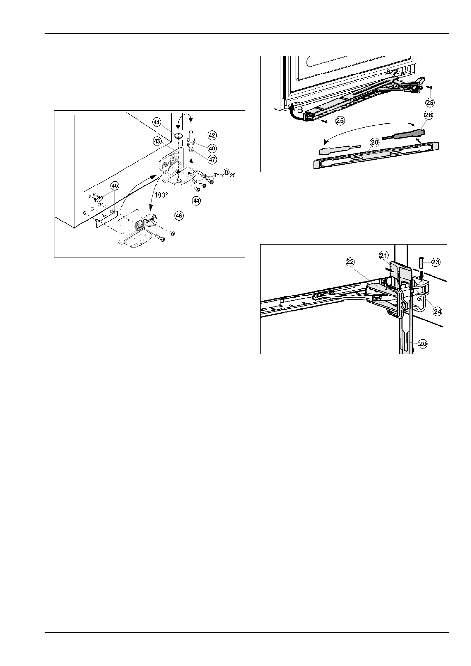
4.3.6 Transferring the lower bearing elements
Fig. 12
u
Lift out the bearing pin
Fig. 12 (42)
together with washer
Fig. 12 (40)
and adjustable-height foot
Fig. 12 (47)
.
u
Lift off the stopper
Fig. 12 (48)
.
u
Unscrew the turn hinge
Fig. 12 (43)
.
u
Carefully lift off the cover on the handle side and stopper
Fig. 12 (45)
and transfer them to the opposite side.
u
Screw the bottom turn hinge
Fig. 12 (43)
firmly into place
(with 4 Nm) on the new hinge side, possibly using a cord-
less screwdriver.
u
Unscrew the bearing element
Fig. 12 (46)
, turn it through
180° and screw it back firmly into place, always screw the
long screw into the oblong hole!
u
Re-insert the stopper
Fig. 12 (48)
into the other hole.
u
Re-insert the bearing pin
Fig. 12 (42)
together with the
washer and adjustable-height foot. In so doing, pay attention
that the locating lug points backwards
4.3.7 Fitting the lower door
u
Place the door from above onto the lower bearing pin
Fig. 12 (42)
.
u
Close the door.
u
Place the plastic cap
Fig. 11 (33)
back onto the middle turn
hinge
Fig. 11 (31)
.
u
Place the middle bearing pin
Fig. 11 (32)
in the lower door,
on the new hinge side, through the middle turn hinge
Fig. 11 (31)
.
u
Attach the washer
Fig. 11 (34)
to the middle bearing pin
Fig. 11 (32)
.
4.3.8 Fitting the lower soft stop mechanism
Fig. 13
u
Remove the cover
Fig. 13 (26)
from the faceplate
Fig. 13 (20)
and re-insert it at the other side.
u
Engage the soft stop unit with the joint pointing to the hinge
side (A) and swivel into place (B).
w
The screw holes at the left and right have to register.
u
Screw the soft stop unit firmly into place (2 x Torx® 15)
Fig. 13 (25)
.
Fig. 14
u
Attach the faceplate
Fig. 14 (20)
to the soft stop bracket so
that the catches face forwards and the front faces the appli-
ance.
u
Draw the soft stop bracket
Fig. 14 (24)
towards the bearing
part and insert the pin
Fig. 14 (23)
from above so that the
square sits in the recess.
u
Attach and engage the cover
Fig. 14 (21)
.
w
Pay attention that the cover fits properly so that the door
closes properly and the pin is secured.
u
Twist the safety lock
Fig. 14 (22)
for removal.
u
Snap the faceplate
Fig. 14 (20)
onto the door.
u
Close the lower door.
4.3.9 Fitting the upper door
u
Place the upper door on the middle bearing pin
Fig. 11 (32)
.
u
Insert the upper turn hinge
Fig. 8 (12)
in the door on the new
hinge side.
u
Screw the upper turn hinge firmly into place (with 4 Nm)
(2xTorx® 25)
Fig. 8 (13)
. Possibly make preliminary holes
with a bradawl or use a cordless screwdriver.
u
Snap the cover
Fig. 8 (11)
and cover
Fig. 8 (10)
into place at
the opposite side.
u
Leave the upper door open.
Putting into operation
8
* Depending on model and options