Parking brake adjustment – Briggs & Stratton 500Z - 26 User Manual
Page 15
500Z 26HP - 48” Mower Deck
1/2008
15
TP 300-7368-IR-ZT-N
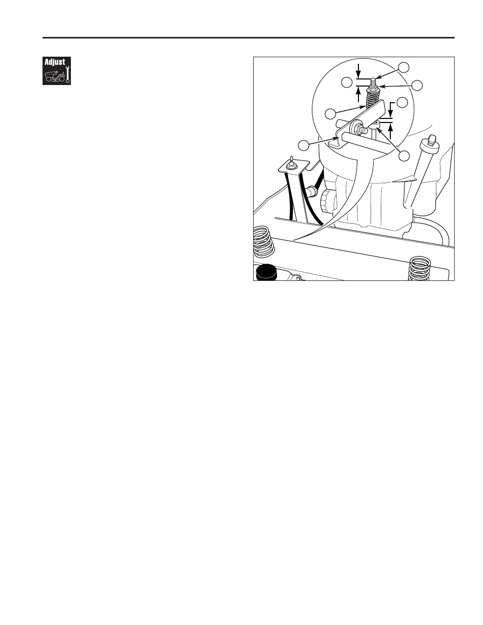
Parking Brake
Adjustment
1. Disengage the PTO, stop the engine, engage the
parking brake, and remove the key from the ignition.
2. Raise the seat plate to gain access to the parking
brake components.
3. Measure the distance from the top of the brake
spring rod (C, Figure 23) to the top of the lock nut
(D) on both sides of the unit. The measurement
should be .50” (1,27 cm). If not, adjust the locknut to
achieve the measurement of .50” (1,27 cm)
4. Measure the distance between the bottom of the
brake shaft weldment (G) and the top of the set
collar (F). The measurement should be .375” (0,95
cm). If not, position the set collar until the
measurement equals .375” (0,95 cm).
Figure 23. Parking Brake Adjustment
A. Brake Spring
B. First Measurement - .50” (1,27 cm)
C. Brake Spring Rod
D. Lock Nut
E. Second Measurement - .375” (0,95 cm)
F. Set Collar
G. Brake Shaft Weldment
A
B
E
G
C
D
F
- 1695284 (14 pages)
- Axion 7800378 (18 pages)
- SNAPPER 7800757 (24 pages)
- INTEK AND QUANTUM 120000 (20 pages)
- 277110TRI (28 pages)
- 196400 (76 pages)
- 7800189 (20 pages)
- 123K00 0134 (13 pages)
- Easy start R5055H 5.5 HP (28 pages)
- 5900619 (52 pages)
- SNAPPER 7800752 (24 pages)
- Harrier 41 (36 pages)
- SNAPPER LT-125 (48 pages)
- NSPV21675 (22 pages)
- 445700 (12 pages)
- 406700 (20 pages)
- 21C200 (12 pages)
- 5901070 (98 pages)
- HERITAGE TRACTOR 131F (36 pages)
- HIDRO DRIVER ZTR 5900682 (72 pages)
- 20G400 (12 pages)
- SNAPPER GT23540 (58 pages)
- 76065 (1 page)
- SP21 (30 pages)
- 205300 (20 pages)
- FM3300 (20 pages)
- 1628 (36 pages)
- SNAPPER 7085625 3013523BVE (56 pages)
- 1694561 (4 pages)
- 1695353 (16 pages)
- MOWER (62 pages)
- 5900683 (50 pages)
- 94200 (20 pages)
- 1695354 (18 pages)
- 7800692 (36 pages)
- Ram Mag 50 / 968999651 (88 pages)
- Snow Series (24 pages)
- 5900664 (19 pages)
- Series 410 thru 420 (16 pages)
- Electric Lawnmower (28 pages)
- 5900703 (16 pages)
- 21A400 (16 pages)
- AA0201 (9 pages)
- MS-5158-5/03 (10 pages)
- 37641401 (12 pages)