Adjustment procedures, Seat adjustment, Ground speed control adjustment – Briggs & Stratton 500Z - 26 User Manual
Page 13
500Z 26HP - 48” Mower Deck
1/2008
13
TP 300-7368-IR-ZT-N
Adjustment
Procedures
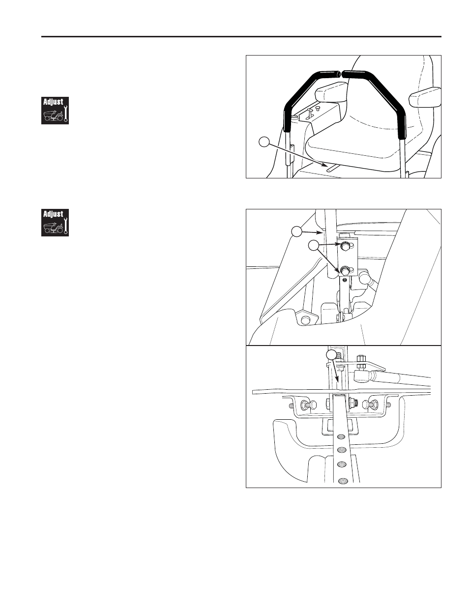
Seat Adjustment
See Figure 20. The seat can be adjusted forward and
backward. Move the seat adjustment lever towards the
left, position the seat as desired, and release the seat
adjustment lever to lock the seat into position.
A
Figure 20. Seat Adjustment
A. Seat Adjustment Lever
Ground Speed Control
Adjustment
The ground speed control levers can be adjusted in
three ways. The alignment of the control levers, the
placement of the levers (how close the ends are to one
another) and the height of the levers can be adjusted.
TO ADJUST THE HANDLE ALIGNMENT
Loosen the mount bolts (A, Figure 21) and pivot the
ground speed control lever(s) (B) to align with each
other.
TO ADJUST THE HANDLE PLACEMENT
Loosen the jam nuts and adjust the placement bolt (C) in
or out to properly adjust the ground speed control lever
end spacing.
TO ADJUST THE HANDLE HEIGHT
Remove the mounting hardware and reposition the
ground speed control lever either up or down from its
original position. You will need to readjust the ground
speed control lever alignment as described above.
Figure 21. Control Lever Adjustment
A. Placement Hardware
B. Ground Speed Control Lever
C. Alignment Hardware
A
B
C