Figure 15, Dc p, Dc plug connections – Brocade Communications Systems Brocade 6910 Ethernet Access Switch 53-1002580-01 User Manual
Page 30
16
Brocade 6910 Ethernet Access Switch Hardware Installation Guide
53-1002580-01
Connecting to a Power Source
2
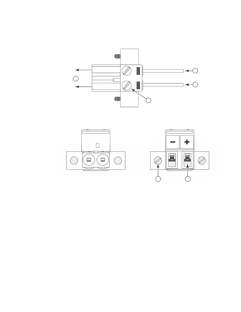
FIGURE 15
DC PLUG CONNECTIONS
1. To switch
2. DC power ground / return
3. -48 VDC power feed
4. Screw-down connector
5. Screw into DC tapped hole on switch
6. DC power line in
Front View
Top View
Rear View
4
1
5
6
2
3