Figure 6, Table 1 – Brocade Communications Systems Brocade 6910 Ethernet Access Switch 53-1002580-01 User Manual
Page 20
6
Brocade 6910 Ethernet Access Switch Hardware Installation Guide
53-1002580-01
Description of Hardware
1
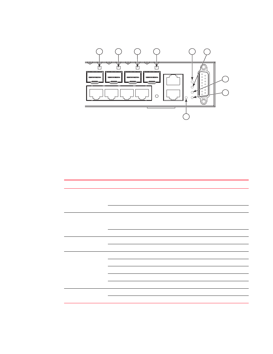
FIGURE 6
PORT AND SYSTEM LEDs
1. Port Status LEDs
2. Major Alarm LED
3. Minor Alarm LED
4. Diag LED
5. Power LED
6. Mgmt LED
TABLE 1
SYSTEM STATUS LEDs
LED
Condition
Status
Major Alarm
Green
Indicates presence within the system of one or more major
traffic-affecting system alarm(s) that are not masked by the
alarm filter.
Off
System is operating normally.
Minor Alarm
Green
Indicates presence within the system of one or more minor
traffic-affecting system alarm(s) that are not masked by the
alarm filter.
Off
System is operating normally.
Diag
Amber
System self-diagnostic is in progress.
Green
System self-diagnostic test successfully completed.
Mgmt
Green
The management port has a valid 1000BASE-T link.
Flashing Green
Flashing indicates 1000BASE-T activity on the port.
Amber
The management port has a valid 10/100BASE-TX link.
Flashing Amber
Flashing indicates 10/100BASE-TX activity on the port.
Off
The link is down.
Power
Green
DC or AC power is functioning normally.
Off
External power not connected or has failed.
3
1
2
6
1
12
11
10
9
1
1
4
5