Able 2 — matching indoor units to outdoor units – Bryant 619FNQ User Manual
Page 2
—2—
INSTALLATION
I. STEP 1 — COMPLETE PRE-INSTALLATION CHECKS
A. Unpack Unit (See Fig. 1)
Move the unit to final location. The grille panel and the
remote control are packed separately for maximum protec-
tion. Remove unit from carton, being careful not to lift the
unit by the condensate drain discharge pipe or by the refrig-
erant connections. Handle by the four corners of the unit.
See Table 1 for field-supplied installation materials required
for installation.
B. Inspect Shipment
File a claim with the shipping company if shipment is dam-
aged or incomplete. Check the unit nameplates to ensure
units match job requirements.
C. Consider System Requirements
Consult local building codes and NEC for special installation
requirements. Use only designated indoor units with outdoor
units. See Tables 2-4B.
See Fig. 2 for unit dimensions. Allow sufficient space for air-
flow clearance, wiring, refrigerant piping, and servicing
units.
Avoid mounting the unit in areas that are:
• exposed to direct sunlight
• too close to heat sources
• damp or in areas exposed to water
• located in areas that could obstruct air circulation, such
as near curtains or furniture
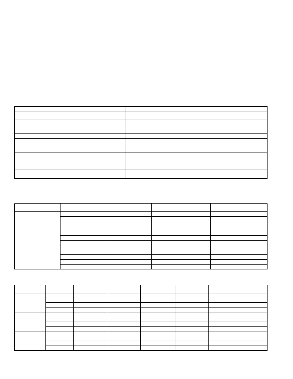
Table 1 — Field-Supplied Installation Materials
LEGEND
T
able 2 — Matching Indoor Units to Outdoor Units*
*All units use R-410A refrigerant only.
Table 3 — AccuRator* Control Sizes and Refrigerant Charge Requirements
*AccuRator controls are for outdoor units. See the outdoor installation instructions for more information.
†The outdoor unit is either fully charged or under charged from the factory.
NAME
SPECIFICATIONS
Connection Pipe
619FNF018,024/FNQ01824:
5
/
8
in. (Mixed Phase)/
3
/
8
in. (Liquid)
619FNF, FNQ03036:
3
/
4
in. (Mixed Phase)/
3
/
8
in. (Liquid)
Wall Sleeve
—
Wall Cap
—
Finishing Tape
PVC Film
Fastening Tape
—
Tube Insulation
—
Drain Hose
1 in. ID
Sealer Putty
—
Outdoor Power Supply Cable
619FNF018-03036: AWG 14
619FNQ01824-03036: AWG 12
Control Wire Electrical Connecting Cable
Between Indoor and Outdoor Unit
Cable Type: AWG 22 synthetic rubber insulation with
Neoprene coating, according to NEC codes.
Wire Nuts
—
Conduit
—
AWG — American Wire Gage
NEC
— National Electrical Code
SYSTEM
TYPE
SYSTEM SIZE
OUTDOOR
UNIT
INDOOR UNIT
MODEL NUMBER
INDOOR UNIT
GRILLE ITEM NUMBER
Cooling Only
018
538ENF018000
619FNF018000
619FN9005
024
538ENF024000
619FNF024000
619FN9006
030
538ENF030000
619FNF030360
619FN9006
036
538ENF036000
619FNF030360
619FN9006
Cooling with
Electric Heat
018
538ENF018000
619FNQ018240
619FN9006
024
538ENF024000
619FNQ018240
619FN9006
030
538ENF030000
619FNQ030360
619FN9006
036
538ENF036000
619FNQ030360
619FN9006
Heat Pump
018
538QNF018000
619FNQ018240
619FN9006
024
538QNF024000
619FNQ018240
619FN9006
030
538QNF030000
619FNQ030360
619FN9006
036
538QNF036000
619FNQ030360
619FN9006
SYSTEM
TYPE
SYSTEM
SIZE
COOLING
ACCURATOR
HEATING
ACCURATOR
ACCURATOR
TYPE
FACTORY
CHARGE† (lb)
ADDITIONAL FIELD
CHARGE REQUIRED† (lb)
Cooling Only
018
0.049
—
B
4.8
0.0
024
0.057
—
B
5.3
1.2
030
0.061
—
B
5.0
3.0
036
0.074
—
B
7.0
2.3
Cooling with
Electric Heat
018
0.049
—
B
4.8
0.0
024
0.057
—
B
5.3
1.2
030
0.061
—
B
5.0
3.0
036
0.074
—
B
7.0
2.3
Heat Pump
018
0.051
0.046
B
5.5
0.0
024
0.055
0.053
B
6.9
0.0
030
0.063
0.055
B
10.7
1.8
036
0.07
0.063
B
10.5
0.0