3 input balance for yprpb signals, Input balance for yprpb signals, Image menu – Barco RLM G5I PERFORMER R9010320 User Manual
Page 83
8. Image Menu
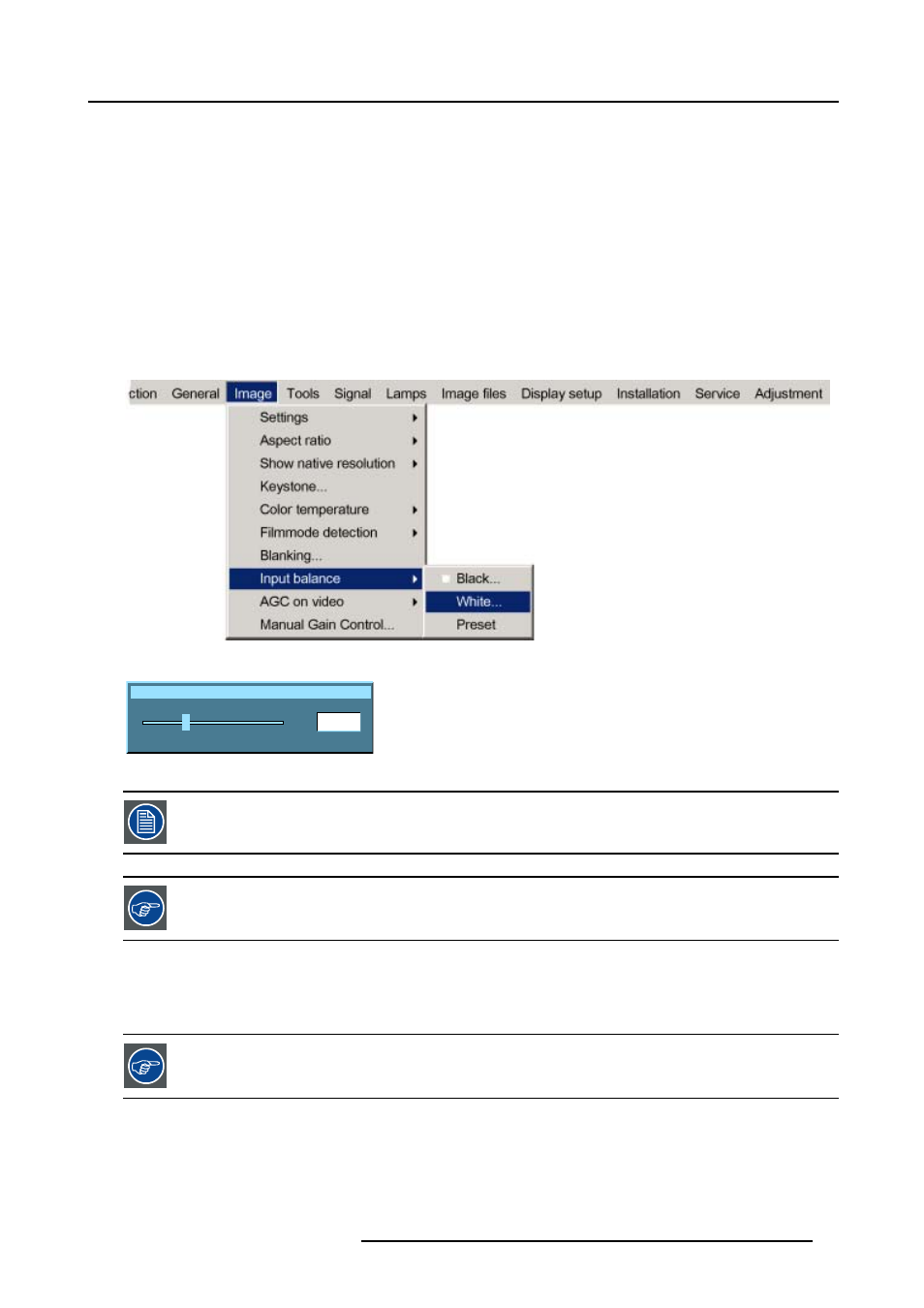
6. Use ↑ or ↓ to select Input balance.
7. Press → to pull down the menu.
8. Use ↓ or ↑ to select White balance. (image 8-41)
9. Adjust the Red white level (gain) on a minimal value. (image 8-42)
10.Adjust the blue white level (gain) on a minimal value
Note:
This minimal value is not necessary , provided that the 2 other colors are not influencing too much the color to be adjusted,
in fact the aim is to minimize the effect of the two other colors since there is a risk of reaching too soon the transition
(bright spots) due to the contribution of these two other colors signals.
11.Adjust the Green white level (gain) until bright spots appear on the screen
12.Adjust the Blue white level (gain) until bright spots appear on the screen
13.Adjust the Red white level (gain) until bright spots appear on the screen
The projected image should now be noisy neutral grey.
Image 8-41
Input white balance Red
50
0
127
Image 8-42
If one uses a gray scale pattern, the bright spots should appear in the white bar.
Selecting Preset restores the factory input balance setting
8.9.3
Input balance for YPrPb signals
Remark on the input balance of a component video source
Before starting the Input Balance procedure, generate a signal with dominant white parts.
R5976815 RLM G5I PERFORMER 02/06/2006
81