0 configuration – B&B Electronics High Speed Asynchronous to Synchronous Converter 2011 User Manual
Page 5
2011AS3297 Manual
3
B&B Electronics -- PO Box 1040 -- Ottawa, IL 61350
PH (815) 433-5100 -- FAX (815) 434-7094
3.0 CONFIGURATION
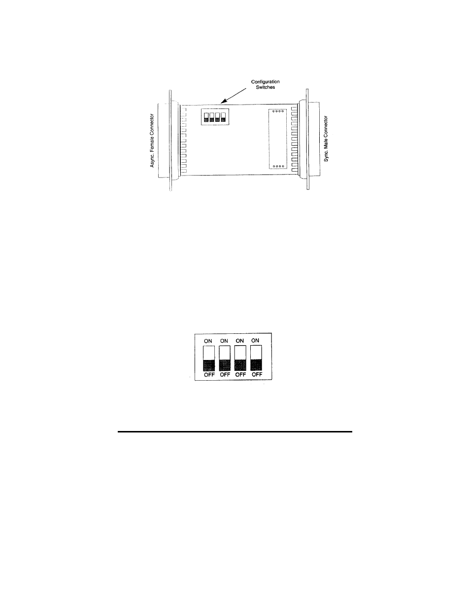
The Model 2011 is configured using internal DIP switches. Figure 1
shows the location of the Model 2011's configuration switches.
Figure 1. Switch locations on the Model 2011 PC board
3.1 ACCESSING INTERNAL SWITCHES
The Model 2011's DIP switches are mounted on the PC board. To
access the PC board, insert the blade of a small flathead screwdriver into
the slot on one side of the Model 2011's case, then pop the case open by
twisting the blade. Repeat on the other side of the case. You should now be
able to pull the case halves apart and access the DIP switches on the PC
board. Once you have set the switches properly, align the case halves and
snap them together.
3.2 SETTING INTERNAL SWITCHES
Three DIP switches are used to configure the Model 2011: two
switches set the character length and one switch matches the signaling
rates of the asynchronous and synchronous ports. Figure 2 shows the
orientation of the DIP switches.
Figure 2. DIP switch orientation