Whirlpool LTG5243DQ User Manual
Page 8
Panel G
You have
successfully installed your
new washer/dryer.
To get the most efficient use from
your new washer/dryer, read your
Use and Care Guide.
Congratulations!
Keep Installation Instructions nearby
where you can refer to them.
They’ll make reinstalling your
washer/dryer in
another home as easy as
the first installation.
37.
Read the Use and Care Guide to
fully understand your new washer/dryer.
Open dryer door. Check to be sure lint
screen is in its proper position. Wipe out drum
with damp cloth to remove any dust.
38.
Plug power supply cord into
grounded outlet. Now start the washer and
allow it to complete the regular cycle.
39.
Start dryer to remove air from the
gas supply line. Using a full heat cycle (not
the air cycle), let the dryer run for at least five
minutes. If the burner does not ignite and you
do not feel heat inside the dryer, shut off the
dryer for five minutes. Check that all gas
supply valve controls are in the “ON” position
and that the power supply cord is plugged
in. Repeat the five-minute test.
34.
Check that you have all of your
tools.
35.
Turn on water faucets and check
for leaks. Tighten couplings if there is leaking.
DO NOT OVERTIGHTEN; this could cause
damage to faucets.
36.
Replace access panel. Be sure to
tighten the two Phillips-head screws at the
top of the access panel.
Phillips
screwdriver
diagonal
cutters
utility
knife
adjustable
wrench
(two may
be
required)
flat-blade
screwdriver
gloves
safety glasses
clamp
level
pliers
slip-joint pliers
33.
Check that
you removed all the
shipping pieces including
the round shipping piece.
Dispose of all materials in
proper manner.
If you do not remove the
round shipping piece,
your washer/dryer may
“walk” away from its
location.
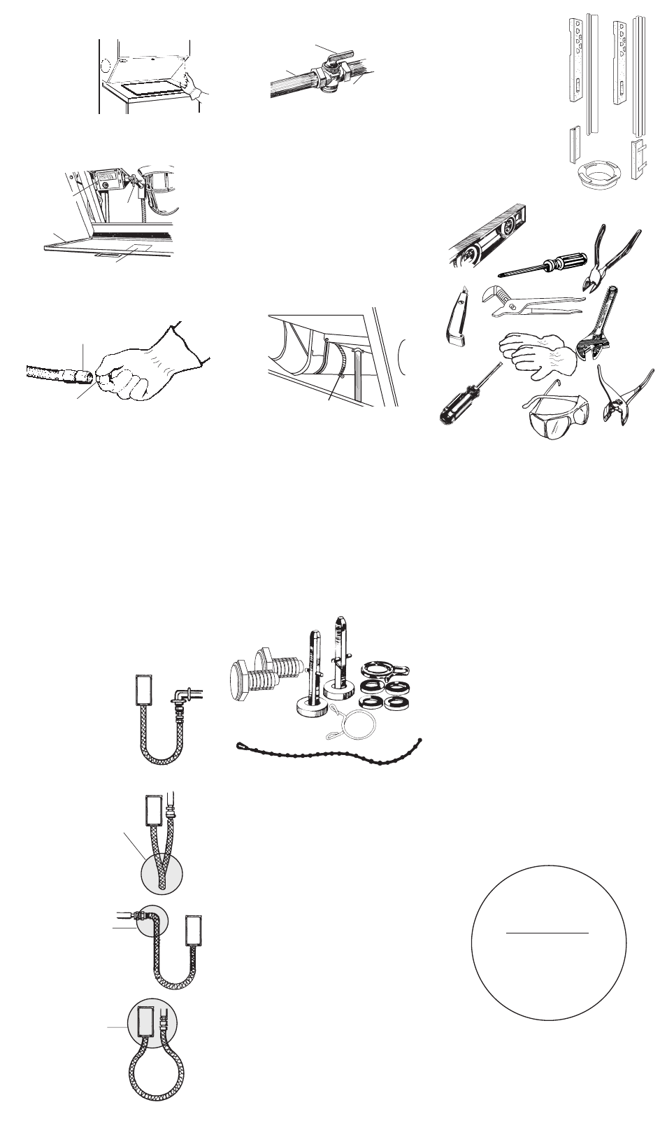
26.
Remove the red cap from the
flexible gas connector. Remove the adapter
from the flexible gas connector. (It may be
necessary to use two adjustable wrenches.)
Install the adapter on the rigid gas supply line
using pipe-joint compound. Attach the
flexible gas connector to the adapter. Do Not
use pipe-joint compound. See Step I, Panel B.
Connect dryer to rigid gas supply line so that
there is a natural loop in the flexible gas
connector from the dryer. The couplings
should be in the same plane and positioned
just far enough apart to allow the flexible gas
connector from the dryer to loop without any
strains on the line. The flexible gas connector
must NOT be twisted, kinked or attached with
any sharp bends. Use pipe-joint compound
resistant to the action of L.P. gas for all gas
connections, except at the flexible gas
connector to the adapter. See Step I,
Panel B.
A rigid gas supply line to washer/dryer
location must be used.
conversion
kit part nos.
open
position
access
panel
wiring
diagram
The wiring diagram is located on the back of the
access panel. Read before installing or servicing.
adapter
red cap
Right method
Wrong methods
The flexible gas connector
MUST be connected in a
single, natural loop.
Gas supply line coupling
should be 38 inches min.
to 41 inches max. from
floor and against (parallel
to) wall.
DO NOT OFFSET
COUPLINGS — this causes
twisting and straining of
the flexible gas connector,
which may cause
premature failure of the
connector.
A sharp bend in the
flexible gas connector
at the couplings causes
straining and twisting,
which may result in
premature failure of the
connector.
Placing the couplings
too close together
causes double bends
that may result in
fatigue failure of the
fittings.
27.
All connections must be wrench-
tightened. Open the shutoff valve in the gas
supply line.
28.
Use a brush and liquid detergent
to test all gas connections for leaks. Bubbles
around connections will indicate a leak. If a
leak appears, shut off gas valve controls and
adjust connections. Then check connections
again.
29.
Determine the length of exhaust
vent that is needed to connect the dryer to
the exhaust hood. See “Exhaust
requirements,” Panel C.
30.
Connect exhaust vent to
washer/dryer and then to the exhaust hood.
• Use the straightest path possible to avoid
90° turns.
• Use clamps to seal all joints in the exhaust
system.
• Use caulking compound to seal exterior
wall opening around exhaust hood.
31.
CHECK ELECTRICAL
REQUIREMENTS. BE SURE YOU HAVE CORRECT
ELECTRICAL SUPPLY AND RECOMMENDED
GROUND METHOD. Check the Installation
Instructions to see that you have completed
each step. Complete any missed steps
before you continue.
25.
If you did not
remove the
access panel in
Step 19, remove
the two foam
shipping pieces
between the
washer and dryer and place with other
shipping pieces. Remove the two Phillips-
head screws located at the top of the
access panel. Set panel and screws aside.
to
dryer
shutoff valve
“open”
position
gas
supply
line
32.
Check that all parts are now
installed. See parts list, Step 3, Panel D. If
there is an extra part, go back through steps
to see which step was skipped.