Wiring diagrams, Page 17 service (cont.) on/off switch – Bunn CWT-TS User Manual
Page 17
Page 17
SERVICE (cont.)
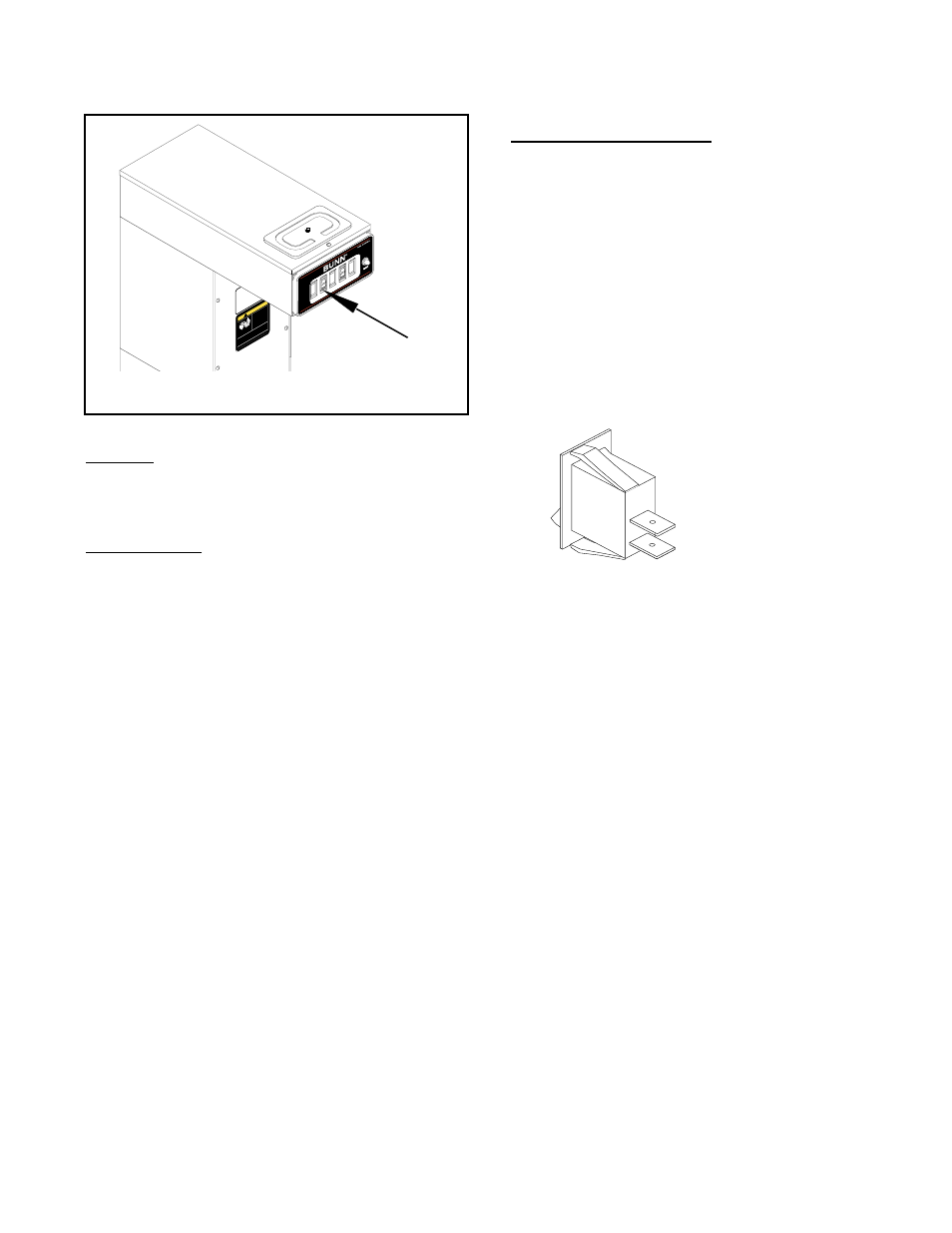
ON/OFF SWITCH
BUNN
MA
NU
FA
CT
UR
ED
B
Y
BU
NN
-O
-M
AT
IC
C
OR
PO
RA
TIO
N
S
PR
IN
GF
IE
LD
, IL
LIN
OI
S,
U
.S
.A
.
MO
DE
L
S/
N
VO
LT
S
A
.C
.
A
MP
W
AT
TS
PH
AS
E
W
IR
E
HE
RT
Z
CO
VE
RE
D
UN
DE
R
ON
E
OR
M
OR
EO
F T
HE
FO
LL
OW
IN
G
PA
TE
NT
S
:
ON
E
OR
M
OR
E
OT
HE
R
PA
TE
NT
S
MA
Y
BE
P
EN
DI
NG
!
CAUTION
FU
NN
EL
C
ON
TE
NT
S
AR
E
HO
T
DI
SC
AR
D
DE
CA
NT
ER
IF:
• C
RA
CK
ED
• S
CR
AT
CH
ED
• B
OI
LE
D
DR
Y
• H
EA
TE
D
W
HE
N
EM
PT
Y
• U
SE
D
ON
H
IG
H
FL
AM
E
O
R
EX
PO
SE
D
EL
EC
TR
IC
E
LE
ME
NT
S
PN: 00658.0000D 3/97 © 1985 BUNN-O-MATIC CORPO
RATION
RE
AD
TH
E
EN
TIR
E
OP
ER
AT
IN
G
MA
NU
AL
BE
FO
RE
U
SI
NG
TH
IS
P
RO
DU
CT
FAILURE TO COMPLY RISKS INJURY
Location:
The ON/OFF switch is located on the left front of
the hood.
Test Procedure:
1.
Disconnect the brewer from the power source.
2.
Viewing the switch from the back remove the
white wire from the upper terminal and the black
wire from the center terminal.
3.
Check the voltage across the white wire and the
black wire with a voltmeter. Connect the brewer
to the power source. The indication must be 120
volts ac for two wire 120 volt models and three
wire 120/240 volt models.
4.
Disconnect the brewer from the power source.
If voltage is present as described, reconnect the white
and proceed to #5.
If voltage is not present as described, refer to the
Wiring Diagrams
and check the brewer wiring har-
ness.
5.
With the black wire removed, remove the white/
red wire from the lower terminal.
6.
Check for continuity across the center and lower
terminal with the switch in the "ON" position.
Continuity must not be present when the switch
is in the "OFF" position.
If continuity is present as described, reconnect the
black wire to the center terminal and the white/red
to the lower terminal.
If continuity is not present as described, replace the
switch.
Removal and Replacement:
1.
Remove the wires from the switch terminals.
2.
Compress the clips inside the hood and gently
push the switch through the opening.
3.
Push the new switch into the opening and spread
the clips to hold switch in the hood.
4.
Refer to the illustration below when reconnecting
the wires.