Connections and controls – Bose L1 Model II User Manual
Page 14
6
Venice_Intro.fm
1/07
I
NTRODUCTION
English
Deutsch
Français
Dansk
Español
Italiano
Svenska
Nederlands
Dansk
Italiano
Svenska
Deutsch
Nederlands
English
Français
Español
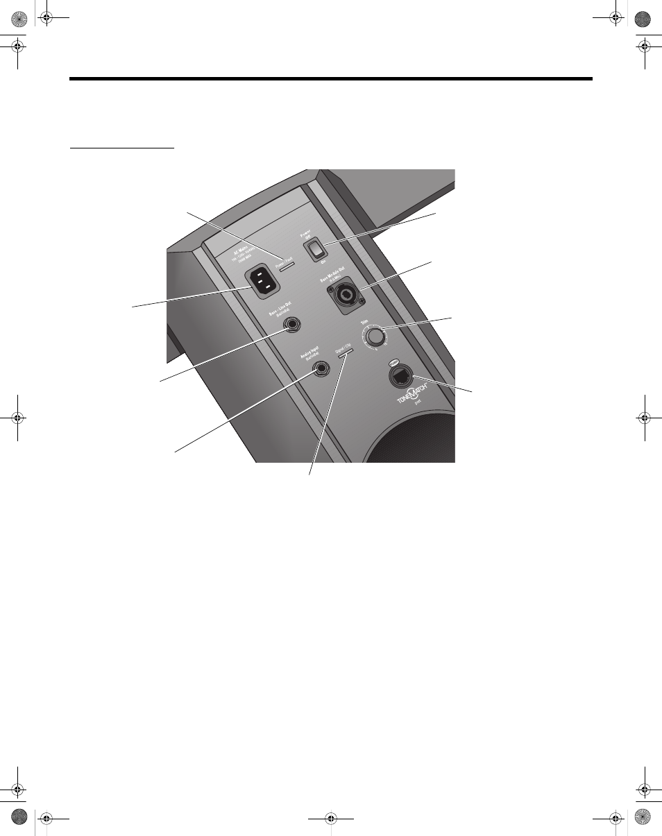
Connections and controls
The top panel of the power stand provides system connectors and controls (Figure 2).
Figure 2
Power stand top panel
Power switch
Switches the system
on and off.
AC Mains
AC power input
connector.
Bass - Line Out
Post-DSP bass signal output.
Accepts a ¼" TRS phone cable.
Used to drive a PackLite
®
power
amplifier.
Bass Module Out
Bass output signal for driving one
or two B1 bass modules. Accepts
a 4-wire bass module cable.
Trim
Adjusts the level of the
analog input signal.
ToneMatch
TM
port
Digital audio and power con-
nection for the optional T1
ToneMatch audio engine.
Accepts the included
ToneMatch cable.
Analog Input
A line-level analog input. Accepts
a ¼" TRS phone cable. Used for
an instrument or other audio
source.
Signal/Clip LED
Indicates status of the analog input signal.
Green = normal input
Yellow = input approaching clipping
Red = input clipping
Power/Fault LED
Indicates power status.
Blue = system on
Red = system fault
Venice_Intro.fm Page 6 Friday, January 19, 2007 8:52 AM