Operator programming instructions, Connecting door locks, Brown/black – Bulldog Security RS602E User Manual
Page 11: Green/black
CONNECTING “TYPE B LOCKS”
• If your vehicle has a “Type B” door locking system,
connect the GREEN WITH BLACK STRIPE wire from the
18-pin harness to the door lock wire. Connect the
BROWN WITH BLACK STRIPE wire to the unlock wire.
See diagram below.
“Type B” - Negative type door locks used on most
imported vehicles and some newer Fords.
BROWN/BLACK
LOCK
UNLOCK
GREEN/BLACK
“Type A” - Positive type door locks used on most
GM, some Chrysler vehicles.
GREEN/BLACK
LOCK
UNLOCK
BROWN/BLACK
CONNECTING DOOR LOCKS
(Optional)
CONNECTING “TYPE A LOCKS”
•If your vehicle has a “Type A” door locking system,
connect the BROWN WITH BLACK STRIPE wire from the
18-pin harness to the door lock wire. Connect the
GREEN WITH BLACK STRIPE wire to the unlock wire.
See diagram below.
CONNECTING “TYPE C LOCKS”
•If your vehicle has a “Type C” door locking
system, you will need to purchase optional part
#778. Once you have purchased the relays, follow
the diagram on page 18 for “Type C” door locks.
TYPE C - (Optional Part #778 required)
Reverse polarity door locks. Used on most GM
trucks, Ford and Chrysler vehicles.
87a
BLACK
RED
BLUE
BLUE
YELLOW
WHITE
BLACK
RED
OPERATOR PROGRAMMING INSTRUCTIONS
10
WE RECOMMEND THAT YOU USE FACTORY SETTINGS FIRST
ENTERING PROGRAMMING MODE
Make sure your vehicle is not running and the brake is pressed. The brake is to remain pressed as long as
you want to remain in programming mode. The unit will exit the programming mode simply by releasing the brake.
The parking lights will flash three (3) times confirming that you are out of programming mode.
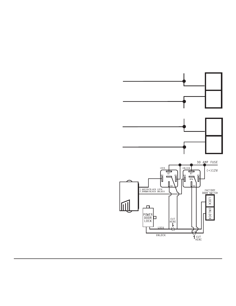
Testing Switch Wire and Motor Wires
Before connecting, you must now determine which wire is the switch wire and which is the motor
wire. Cut both the lock and unlock wires in half. Start with both of the lock wires by placing
the clip end of your test light to ground, hold the door lock switch in the lock position, make
sure you are using the master switch (usually on the driver’s door) and probe both lock wires
looking for voltage. The wire that illuminates the test light, mark as the switch wire, the wire
that shows no voltage, mark as the motor wire. Repeat the procedure for the unlock wire. When
connecting the lock and unlock wires to the #778 relay harness, make sure you connect the switch
wire to the RED wire or pin #87A and the motor wire to the BLUE wire or pin #30. Be sure to connect
the lock wires to the lock relay, and the unlock wires to the unlock relay, you may need to mark
these relays before you start.