Testing door locks – Bulldog Security RS602E User Manual
Page 10
9
HORN HONK OUTPUT (-)
(Optional part #775)
The existing horn wire will usually be found in the main ignition
switch harness in the steering column. Probe for a wire which will
remain neutral (in some cases may show a (+) positive). When the
horn is pressed this wire will test as a ground or (-) negative.
An optional, part #775 will be needed to do this function. Connect
the GRAY WITH BLACK STRIPE wire from the 18-pin harness to the
WHITE wire on the optional part #775. Connect the BLACK wire to
(+)12V constant fused at 10 amps. Connect the BLUE wire to ground,
connect the YELLOW to the horn circuit at the steering column.
Optional part #775
required.
+12 VOLT FUSED
AT 10 AMPS
87a
TO HORN WIRE
GRAY/BLACK
FROM 18-PIN
HARNESS
YELLOW
BLACK
WHITE
BLUE
THE RED WIRE IS NOT USED,
TAPE OFF.
RED
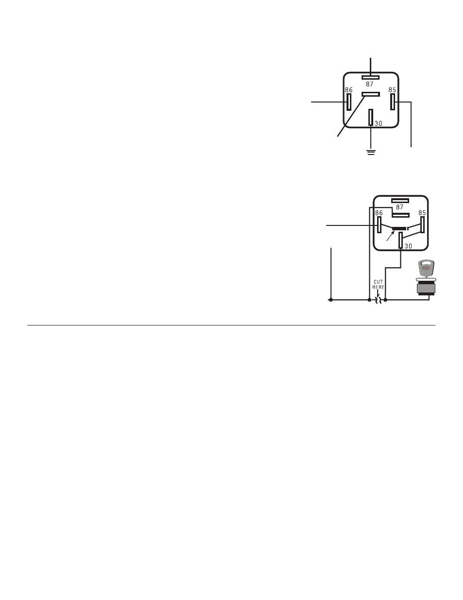
INSTALLING STARTER IMMOBILIZER (-) Output (Optional part #773)
Locate the same starter/crank wire located in the main wiring harness
that you have tied the YELLOW WITH BLACK STRIPE wire from the 4-relay
harness into. Cut the starter/crank wire in half, making sure that the
YELLOW WITH BLACK STRIPE wire from the relay harness stays on the
“starter side” and not the “switch side” of your starter immobilizer
circuit. Connect the RED wire from the starter immobilizer to the
“switch side” of the starter/crank wire then connect the WHITE wire
to the “starter side” of the starter/crank wire. Connect the ORANGE
wire from the starter immobilizer to the ORANGE wire on the 18-pin
harness. NOTE: You will need to cut factory wiring to make an end to
end connection, see “Making Connections” on pages 3-4.
87a
ORANGE
on immobilizer
STARTER SIDE
SWITCH SIDE
WHITE
RED
Diode
YELLOW WITH
BLACK STRIPE
WIRE from
4-relay
harness
TESTING: Door Locks (OPTIONAL)
There are three basic types:
“Type A” Door Lock Test (Most GMs and most Chryslers)
Probe both of your door lock wires going to the door lock switch usally located in the driver’s kick
panel, attach the clip end of your test light to a good chassis ground. Using the vehicle’s door lock
controls, activate the lock then the unlock, testing both wires one at a time. If one of these wires
tests (+) positive when lock is pressed and the other tests (+) positive when they are unlocked, your
vehicle has a “Type A” door locking system. Make sure to mark which wire is lock and unlock. Proceed
to connecting Door Locks. NOTE: “Type A” and “Type C” locks will test the same, until you test for ground.
Make sure you run both tests before making your connections.
“Type B” Door Lock Test (Most Imports, some newer Fords)
Probe both of your door lock wires going to the door lock switch usally located in the driver’s kick
panel, attach the clip end of your test light to +12V. Using the vehicle’s door lock controls, activate
the lock then the unlock testing both wires one at a time. If the test light illuminates when you probe
the lock and the unlock wires your vehicle has a “Type B” door locking system. Make sure to mark which
wire is lock and unlock. Proceed to Connecting Door Locks.
TESTING DOOR LOCKS
“Type C” Door Lock Test (Most Fords, some Chryslers, GM Trucks)
Using your test light probe both the lock and the unlock wires usually located in the driver’s
kick panel. Attach the clip end of your test light to ground probing both wires one at a time while
locking and unlocking the doors with the driver’s side switch (usually the master switch). The
test light should illuminate in both switch positions. Now attach the clip end of your test light
to +12V constant, probe both wires one at a time again. The light should then illuminate again
only in reverse order. This tells you that you have a “Type C” reversing polarity system. Make
sure to mark which wire is lock and unlock.