Bryant 3-PHASE 602A User Manual
Page 9
VII.
INSTALL ELECTRICAL CONNECTIONS
WARNING: The unit cabinet must have an uninter-
rupted, unbroken electrical ground to minimize the pos-
sibility of personal injury if an electrical fault should
occur. This ground may consist of an electrical wire
connected to the unit ground lug in the control compart-
ment, or conduit approved for electrical ground when
installed in accordance with NEC, ANSI/NFPA Ameri-
can National Standards Institute/National Fire Protection
Association (latest edition) (in Canada, Canadian Electri-
cal Code CSA C22.1) and local electrical codes. Failure
to adhere to this warning could result in serious injury or
death.
CAUTION: Failure to follow these precautions could
result in damage to the unit being installed:
1. Make all electrical connections in accordance with
NEC ANSI/NFPA (latest edition) and local electrical
codes governing such wiring. In Canada, all electrical
connections must be in accordance with CSA standard
C22.1 Canadian Electrical Code Part 1 and applicable
local codes. Refer to unit wiring diagram.
2. Use only copper conductor for connections between
field-supplied electrical disconnect switch and unit.
DO NOT USE ALUMINUM WIRE.
3. Be sure that high-voltage power to unit is within
operating voltage range indicated on unit rating plate.
On 3-phase units, ensure phases are balanced within 2
percent. Consult local power company for correction
of improper voltage and/or phase imbalance.
4. Insulate low-voltage wires for highest voltage con-
tained within conduit when low-voltage control wires
are in same conduit as high-voltage wires.
5. Do not damage internal components when drilling
through any panel to mount electrical hardware, con-
duit, etc.
A.
HIGH-VOLTAGE CONNECTIONS
The unit must have a separate electrical service with a field-
supplied, waterproof disconnect switch mounted at, or within sight
from the unit. Refer to the unit rating plate, NEC and local codes
for maximum fuse/circuit breaker size and minimum circuit amps
(ampacity) for wire sizing (See Tables 5 and 6 for electrical data).
The field-supplied disconnect may be mounted on the unit over the
high-voltage inlet hole (See Fig. 2 and 3).
If the unit has an electric heater, a second disconnect may be
required. Consult the Installation, Start-Up, and Service Instruc-
tions provided with the accessory for electrical service connec-
tions.
Operation of unit on improper line voltage constitutes abuse and
may cause unit damage that could affect warranty.
B.
ROUTING POWER LEADS INTO UNIT
Use only copper wire between disconnect and unit. The high-
voltage leads should be in a conduit until they enter the duct panel;
conduit termination at the duct panel must be watertight. Run the
high-voltage leads through the power entry knockout on the power
entry side panel. See Fig. 2 and 3 for location and size. When the
TABLE 4—MINIMUM AIRFLOW FOR RELIABLE ELECTRIC HEATER OPERATION (CFM)
SIZE
602A030
602A036
602A042
602A048
602A060
AIRFLOW (CFM)
1000*
1200
1400
1600
2000
* The 030 size models must be run on medium or high speed when used in conjunction with 15 kw electric heat accessory
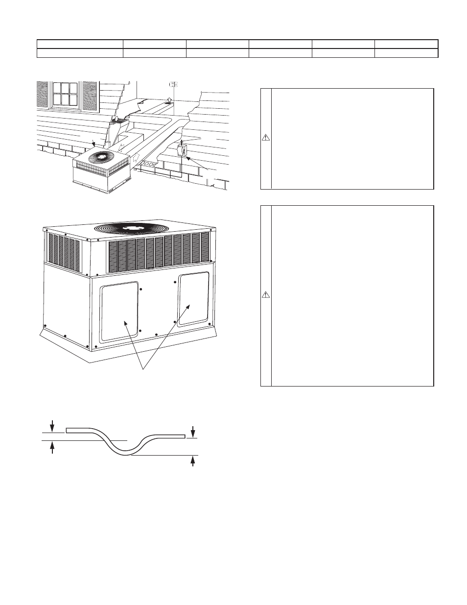
Fig. 9—Typical Installation
C00139
INDOOR
THERMOSTAT
DISCONNECT
PER NEC
FROM
POWER
SOURCE
RETURN
AIR
TOP COVER
Fig. 10—602A with Duct Covers On
(Unit Shown with Optional Louvered Grille)
C99030
Horizontal Duct Covers
Fig. 11—Condensate Trap
C99013
1” (25mm) MIN.
2” (50mm) MIN.
TRAP
OUTLET
—9—