Bryant 3-PHASE 602A User Manual
Page 14
leads are inside the unit, run leads up the high-voltage raceway to
the line wiring splice box (See Fig. 12–17). On all 3-phase units,
connect the leads to the black, yellow, and blue wires (See Fig.
16).
C.
CONNECTING GROUND LEAD TO GROUND LUG
Connect the ground lead to the chassis using the ground lug in the
wiring splice box (See Fig. 16).
D.
ROUTING CONTROL POWER WIRES (24-V)
Form a drip-loop with the thermostat leads before routing them
into the unit. Route the thermostat leads through grommeted,
low-voltage hole provided in unit into unit control power splice
box (See Fig. 2 and 3). Connect thermostat leads to unit control
power leads as shown in Fig. 15.
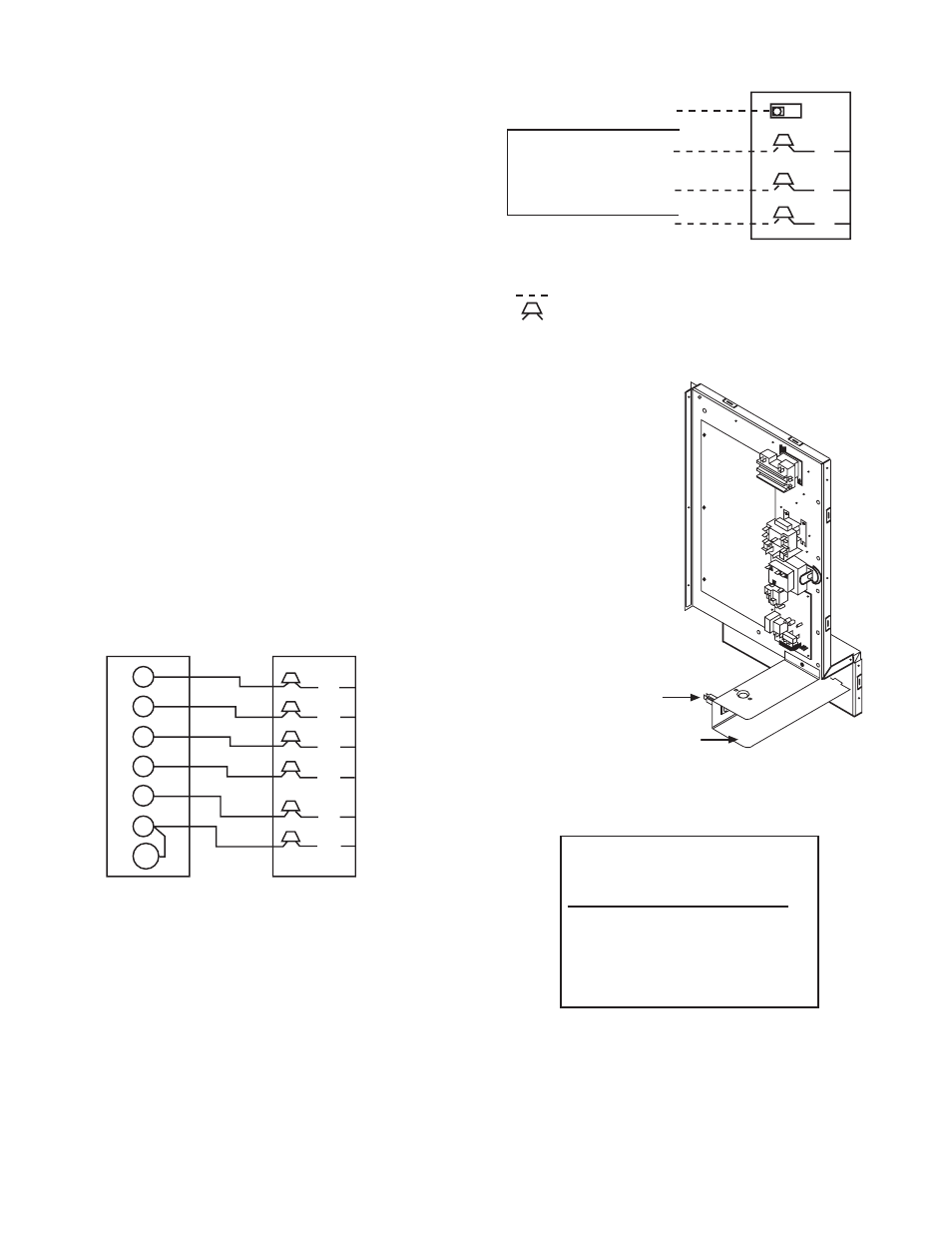
The unit transformer supplies 24-v power for complete system
including accessory electrical heater. An automatic-reset circuit
breaker (See Fig. 17) is provided in the 24-v circuit; see the caution
label on the transformer or Fig. 18. Transformer is factory wired
for 230-v operation. If supply voltage is 208-v, rewire transformer
primary as described in Special Procedures for 208-v Operation
section.
E.
SPECIAL PROCEDURES FOR 208-V OPERATION
1. Disconnect the yellow primary lead from the transformer.
See unit wiring label (See Fig. 12).
2. Connect the yellow primary lead to the transformer terminal
labeled 200-v.
Indoor blower-motor speeds may need to be changed for 208-v
operation. Refer to indoor airflow and airflow adjustments section.
Fig. 15—Control Connections
C99056
Y
C
W2
E
G
R
O
THERMOSTAT
AND SUBBASE
UNIT CONTROL POWER
SPLICE BOX
BRN
WHT
YEL
GRN
RED
ORN
Fig. 16—Line Power Connections
C99057
GROUND LUG
(IN SLPICE BOX)
BLU
YEL
BLK
GROUND
LEAD
SINGLE-PHASE
CONNECTIONS
TO DISCONNECT
PER NEC
3-PHASE
CONNECTIONS
LEGEND
NEC – National Electrical Code
Field Wiring
Splice Connections
NOTE: Use copper wire only.
L1
L3
L2
Fig. 17—Control Wiring Plate
C99070
24 V Circuit Breaker
24 Volt Compartment
Fig. 18—Transformer Label
C99058
TRANSFORMER CONTAINS A MANUAL
RESET OVERCURRENT PROTECTOR
IT WILL NOT AUTOMATICALLY RESET
DISCONNECT POWER AND INSTALL
LOCKOUT TAG PRIOR TO SERVICING
THIS COMPARTMENT MUST BE CLOSED
EXCEPT WHEN SERVICING
—14—