Spa mc 2300, 10 – drives description, Tools mounting and machine reversibility – Briggs & Stratton MC 2300 User Manual
Page 6
SpA MC
2300
6
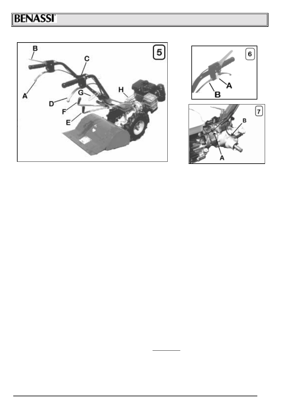
10 – DRIVES DESCRIPTION
A) CLUTCH CONTROL LEVER is used to disengage t he engine from t he tr ans mission, it must be operat ed ever y time you operat e levers and
bef ore st opping the mac hine. The lever is c onnec ted to the ENG INE-STOP (Ref. ”B” - Pict ure 5); To ignite t he mac hine engage and loc k t he
clutch toget her with t he l owered engine-stop, wit h t he pushbutt on outside t he lever (Ref. “A” Picture 6). If the lever is not loc ked, the engine
will not st art sinc e it is earthed. To unloc k t he cl utch lever it is s ufficient t o pull lightl y t he lever upwar ds and the l oc king will be automatic ally
released.
B) ENGINE STO P LEVER the main f uncti on of this s afet y device is to s top immediat ely the engine in t he moment t hat one t akes away his
hands from t he handlebars and t o loc k t he clutch lever in engaged position ( disengagement of the engine from the dri veline organs ) in
order to prevent s udden starting of the mac hine during the ignition phase of t he engine . If the clutch lever is not loc ked wit h the butt on
inside the engine-stop in engaged position, the engine, being connect ed t o eart h, will not start. The engine-st op is also us ed t o switc h off
the engine at the end of the wor k.
C) ACCELERATOR HAND-LEVER permits to increase or decrease the engine R.P.M. (power). By pushi ng it downwards cloc kwis e you
increase R. P.M.; by pushi ng it upwards countercloc kwise you decrease them.
D) WHEEL DISENGAGE LEVER is used t o disengage the wheels from transmission. This lever helps t o move t he machi ne when s witched
off.
E) REVERSE LEVER is used to reverse the mac hine moti on; by pulling the lever in the cultivat or version towards t he dri ving place, t he
mac hine goes f orwards, by pushing it for ward t he machine goes bac kwards. The speed in t he culti vator version is slower than in t he lawn
mower version. A s afet y device does not allow to engage t he reverse gear when t he milling cutter is in motion. See Ref. ”A” Picture 8.
Befor e engaging the reverse gear disengage the milling cutter.
F) P.T.O LEVER is us ed t o engage the power t ake-of f to the diff erent tools. By pus hing the lever f orward, in the lawn mower version, you
disengage t he power t ake-of f, by pulling it t owards the dri ving plac e you engage it . I n t he c ulti vat or version, by pushing f orward you engage
the power take- off and by pulling t he lever towards t he driving place you disengage it.
G) HAND LEVER FOR HANDLEBAR LOCKING is used to adjust the handlebars in t he most c omfortable position to wor k. O nce you have
obt ained t he desired position, you have to tighten the hand lever.
H) HAND LEVER FOR STEERING COLU MN LOCKING is used t o regulat e sideways t he handle and t o 180° reverse the handle itself . By
unscrewing the hand lever you release the steering column, whic h can pi vot; onc e you have obt ained the desired position tighten strongly.
To 180° reverse t he s teering column take off t he reverse levers and P.T.O and put them on again. The hand lever is pawl oper ated (see
hand lever for handlebar loc king ).
! FILLING AND VENT OIL CAP (Ref. ”A” - Picture 7).
! DISCHARGE GEARBOX OIL CAP. (Ref. ”A” Picture 14)
! LEVEL OIL SCREW (Ref. “B” Picture 7)
11- TOOLS MOUNTING AND MACHINE REVERSIBILITY
! It is ver y eas y to mount or to c hange tools to the mac hine. Tools are all quic k coupling type and don’t need screws or fastening spanners
for the loc king.
! Tools ar e coupled in the machi ne body ( male and female) and loc ked with a pin. T he pin must be loc ked with the l ever (Ref. “B” Picture
8) in order to avoi d its disengagement.
! Assure that the tool part (male) to coupl e in the machine body is al ways well lubricated.
! To turn the handl ebar steering column from the Culti vator version (bac k tools) to the Power mower version (front tools) proceed in the
followi ng way:
1) Take off the speed selec tor levers PTO complet ely, unscrew the hand lever steering column (Ref. “H” Picture 5), turn 180° t he steering
column counterclockwise, tight en thoroughl y the hand lever and i nsert the levers again, not f orgetting t o loc k them wit h its cot ter pins,
making t hem pass t hrough the t wo hol es with fairlead on t he left of t he handle support .
2) Take off t he s af et y loc king rod f or reverse gear, (Ref. “A” Picture 8), slippi ng off the t wo s peci al cott er pi ns, (Ref. “C” Picture 8).
! To pass from the Power mower version to the Culti vator version proc eed in the s ame way, turni ng clockwise the steering column. Put
the saf et y loc ki ng rod f or reverse gear again, (Ref. “A” Picture 8).