8 menu system – Bacharach H25-IR User Manual
Page 16
Introduction
H25-IR
10
Instruction 3015-4342
1.8 Menu System
Press the ENT and ESC keys at the same time to access the Main menu. The menu system enables the
operator to perform such functions as setting up the instrument, viewing logged readings, configuring the four
user-defined setups, entering calibration data, and viewing the instrument’s diagnostic readings. The buttons
on the instrument’s front panel and probe are mapped the same and can be used inter-changeably, with
exception of the CAL button.
Select a menu item by first using the Up and Down buttons to highlight the desired item, and then pressing
ENT to select that item and display its data screen. After an item has been selected, use the Left, Right, Up,
and Down buttons to highlight or change data within a screen. Pressing the ENT button saves the new data,
while pressing the ESC button aborts the operation and displays the previous screen.
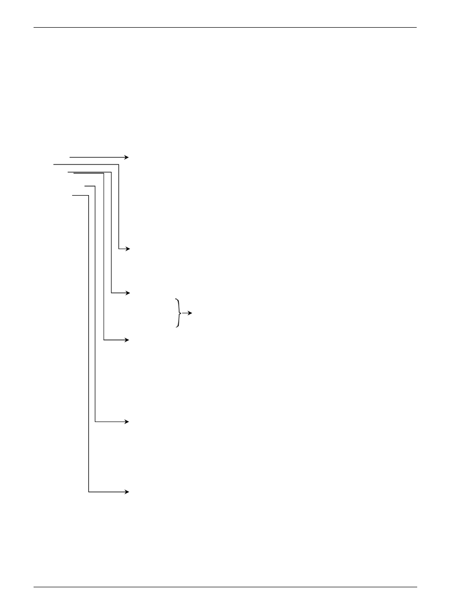
Main Menu:
SYSTEM
System Menu:
LOG GAS
TYPE
........................ Gas being monitored
SETUPS LEAK
UNITS ..................... Leak rate units of measure
CAL DATA
RELAYS ............................ Relay set up for activating external equipment
DIAGNOSTICS LOOP
................................ 4
20 mA signal’s mA per ppm loop factor
FACTORY*
BRIGHTNESS ................... Brightness level of display
CLOCK
.............................. Date and time
PCHK MODE ..................... Determines when a pressure check is performed
PROBE
BUTTON
.............. Selects function of button on the Standard Probe
SERIAL OUTPUT.............Configures serial data format for RS232 output
RESET DEFAULTS ........... Resets user programmable parameters to factory defaults
(Calibration data is not changed)
Log Menu:
VIEW
LOG ......................... View individual logged measurements
CLEAR LOG ...................... Clear total contents of log
LOG TOTAL ....................... View a numerical total of all measurements stored in log (up to 50)
LOG LIMIT ......................... Total accumulated leak setpoint
Setup Menu:
SETUP NAME ..................Text name given to the SETUP selection
SETUP NO.1
RANGE.............................Sensitivity of instrument (small, medium, large)
SETUP
NO.2
GAS
TYPE .......................Gas being monitored
SETUP NO.3
FEEDBACK MODE ..........Gas-level feedback (continuous, setpoint, H25C)
SETUP
NO.4
SETPOINT........................Gas value for the Feedback Mode & Search Auto
SEARCH AUTO ZERO ....Sets condition when auto zero is turned OFF
Calibration Data Menu:
CAL
TYPE............................ Internal
or
external leak source
EXT
RATE............................ Leak
rate of external leak source
EXT GAS TYPE ................... Type of gas in external leak source
CAL FACTOR ...................... Calibration factor
RESTORE FACTORY CAL..... Restores factory leak rate calibration (internal leak source only)
CAL
INTERVAL ................... Allows user to select amount of time between required calibrations
ENFORCE CAL INTERVAL. Allows user to call for calibration at programmed interval
LAST
CAL
DATE ................. Displays
date and time of last calibration cycle performed
Diagnostic Menu:
SENSOR DATA ................. Raw data from all sensors
LAST FAULT...................... List of all current faults, or last fault
IR
EMITTER....................... Infrared emitter’s voltage, amperage, wattage, & resistance
PRESSURE ....................... All
measured pressures
LOOP TEST ....................... Set the 4–20 mA loop output to 0, 4, 10, or 20 mA
CLR LAST FAULT ............. Clear fault list of all faults
AUTO GAIN........ ........
Automatically set digital potentiometer (zero gas applied)
Factory Menu:
AUTO
GAIN ....................... Automatically set digital potentiometer (zero gas applied)
DIGIPOT ............................ Manually set digital potentiometer (zero gas applied)
LEAK
RATE ....................... Leak rate of internal leak source
LEAK
GAS ......................... Gas
type used in internal leak source
LEAK
TEMP ....................... Specified
temperature
for internal leak source in °C
LEAK TEMPCO ................. Temperature coefficient for internal leak source in % per °C
SENSOR
CAL.................... Pressure, temperature, and flow calibration settings
MODEL
SELECT ............... Selects model of unit according to part number
PROBE
TYPE .................... Selects type of probe connected to instrument
FIRMWARE........................ Date firmware was compiled
* The Factory Menu appears only when activated by service technicians who know the correct activation procedure.