Connecting the units setting example, Connection diagram, Setting example – Pioneer RS-A99 User Manual
Page 7: Connecting the units
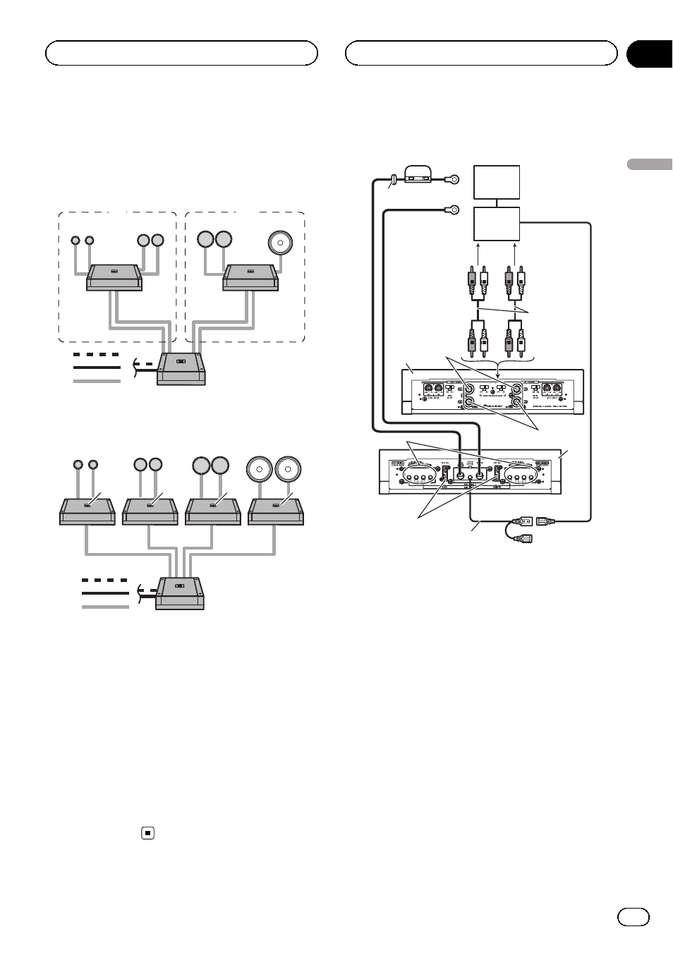
Setting example
In this system, connect this unit to 4 channels
in
1, and 3 channels in 2.
3
8
9
a
d
c
e
f
b
4
5
6
1
2
7
7
In this system, connect 2 channels to each
unit.
d
c
e
f
3
8
7
9
a
b
4
5
6
7
7
7
3 Tweeter
4 Middle-range speaker
5 Low-range speaker
6 Subwoofer
7 This unit
8 High range output
9 Mid range output
a Low range output
b Subwoofer output
c RS-P99 (sold separately)
d Optical cable
e IP-BUS cable
f Analog signal
Connection diagram
1
2
4
3
5
6
9
a
b
c
d
e
f
7
8
1 Special red battery wire
RD-228 (sold separately)
After completing all other amplifier connec-
tions, finally connect the battery wire terminal
of the amplifier to the positive (
+) battery
terminal.
2 Ground wire (Black)
RD-228 (sold separately)
Connect to a clean, paint-free metal location.
3 Car stereo with RCA output jacks (sold sepa-
rately)
4 RS-P99 (sold separately)
5 External output
If only one input plug is used, do not connect
anything to RCA input jack B.
6 Connecting wire with RCA pin plugs (sold se-
parately)
7 RCA input jack A
8 RCA input jack B
En
7
Section
03
Connecting
the
units
Connecting the units