Installing your speaker system, Single), 02 connecting your equipment – Pioneer SC-LX75 User Manual
Page 13: Bi-amping your speakers, Bi-wiring your speakers, Caution
En
13
02
Connecting your equipment
Note
! Please refer to the manual that came with
your speakers for details on how to connect
the other end of the speaker cables to your
speakers.
! Use an RCA cable to connect the subwoofer.
It is not possible to connect using speaker
cables.
! If you have two subwoofers, the second
subwoofer can be connected to the
SUBWOOFER 2 terminal. Connecting two
subwoofers increases the bass sound to
achieve more powerful sound reproduction. In
this case, the same sound is output from the
two subwoofers.
Bi-amping your speakers
Bi-amping is when you connect the high
frequency driver and low frequency driver of
your speakers to different amplifiers for better
crossover performance. Your speakers must be
bi-ampable to do this (having separate termi-
nals for high and low) and the sound improve-
ment will depend on the kind of speakers you’re
using.
High
Low
RS-232C
ZONE2
OUT
CENTER
CU-RF100
FRONT
CENTER
R
L
R
L
SPEAKERS
FRONT HEIGHT
A
FM UNBAL 75
AM LOOP
ANTENNA
(OUTPUT 5 V
150 mA MAX)
CONTROL
IR
OUT
IN
OUT
IN 1
IN 2
2
1
12 V TRIGGER
(OUTPUT 12 V
TOTAL 150 mA MAX)
AUDIO
Bi-amp compatible speaker
CAUTION
! Most speakers with both High and Low
terminals have two metal plates that connect
the High to the Low terminals. These must
be removed when you are bi-amping the
speakers or you could severely damage the
amplifier. See your speaker manual for more
information.
! If your speakers have a removable crossover
network, make sure you do not remove it for bi-
amping. Doing so may damage your speakers.
Bi-wiring your speakers
Your speakers can also be bi-wired if they sup-
port bi-amping.
! With these connections, the Speaker System
setting makes no difference.
CAUTION
! Don’t connect different speakers from the
same terminal in this way.
! When bi-wiring as well, heed the cautions for
bi-amping shown above.
% To bi-wire a speaker, connect two
speaker cords to the speaker terminal on
the receiver.
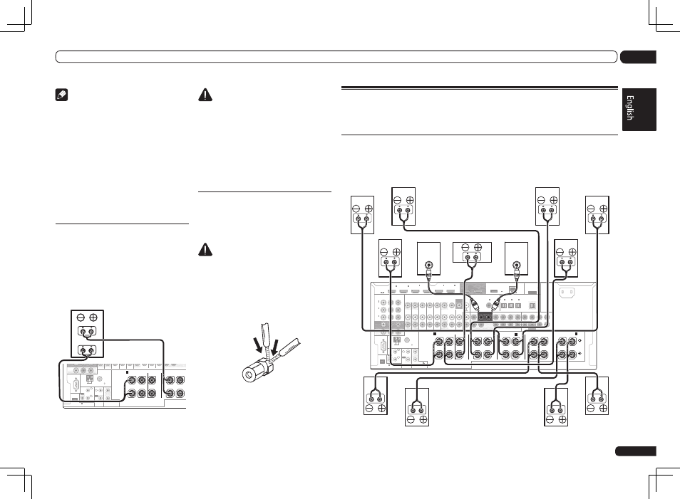
Installing your speaker system
At the very least, front left and right speakers only are necessary. Note that your main surround
speakers should always be connected as a pair, but you can connect just one surround back
speaker if you like (it must be connected to the left surround back terminal).
[A] 9.2 channel surround system (Front height/Front wide) connection
! If necessary, select ‘9.1ch FH/FW’ from the Speaker System menu.
See
Speaker system setting on Operating Instructions in CD-ROM to do this.
! When only connecting one surround back speaker, connect it to the SURROUND BACK L (Single)
terminals.
RS-232C
ZONE 2
IN
IN
IN
IN
DVR/BDR
OUT
OUT
ZONE 3
OUT
TV/SAT VIDEO
IN
PHONO
GND
SIGNAL
CD IN
DVD
OUT 1
(CONTROL)
OUT 2
PRE OUT
MULTI CH IN
SUBWOOFER
1
2
COMPONENT VIDEO
Y
P
B
P
R
ASSIGNABLE
MONITOR
OUT
ZONE2
OUT
(DVD)
IN
1
(DVR/
BDR)
IN
2
(VIDEO)
IN
3
FRONT
CENTER
SURROUND SURR BACK F HEIGHT
F WIDE
L
R
CENTER
FRONT
SURROUND SURR BACK
(
CD)
(
DVD)
COAXIAL
ASSIGNABLE
IN
1
IN
2
(
DVR/BDR)
(
TV/SAT)
OPTICAL
ASSIGNABLE
IN
1
IN
2
IN
3
OUT
(
VIDEO)
(OUTPUT 5 V
0.1 A MAX)
ADAPTER PORT
CU-RF100
DC OUTPUT
for WIRELESS LAN
(10/100)
LAN
(OUTPUT
5 V
0.6 A MAX)
FRONT
CENTER
SURROUND
SURROUND BACK
R
L
R
L
R
L
R
L
R
L
(Single)
(Single)
SPEAKERS
FRONT WIDE /
B
FRONT HEIGHT
A
A
AC IN
FM UNBAL 75
AM LOOP
ANTENNA
(OUTPUT 5 V
150 mA MAX)
CONTROL
IR
OUT
IN
OUT
IN 1
IN 2
2
1
12 V TRIGGER
(OUTPUT 12 V
TOTAL 150 mA MAX)
VIDEO
AUDIO
MONITOR
OUT
HDMI
BD IN
(VIDEO)
IN
1
IN
2
IN
4
(DVD)
IN
5
(DVR/BDR)
IN
6
ASSIGNABLE
1 6
SUBWOOFER
LINE LEVEL
INPUT
LINE LEVEL
INPUT
Front height right
Front height left
Front wide right
Front right
Center
Subwoofer 2
Subwoofer 1
Front left
Surround left
Surround back right
Surround back left
Surround right
Front wide left