Connecting the cdj-2000/cdj-900 and another mixer – Pioneer CDJ-2000-W User Manual
Page 26
6
Connecting the CDJ-2000/CDJ-900 and
another mixer
Connecting rekordbox by wired connection/Connecting a USB device or
SD memory card
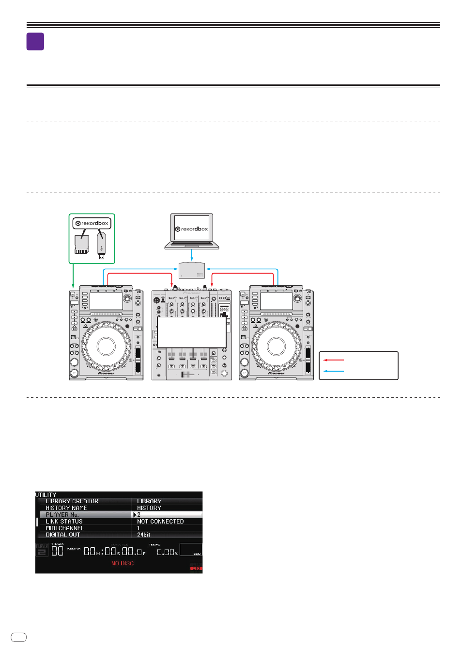
Equipment used
! CDJ-2000 (1 – 4 units) or CDJ-900 (1 – 4 units)
! Switching hub
! Computer (Mac/Windows) on which rekordbox is installed
! USB device or SD memory card on which music files analyzed with rekordbox are stored
! Another DJ mixer (DJ mixer other than the DJM-2000nexus/DJM-2000/DJM-900nexus)
! Audio cable
! LAN cables (one for each DJ player + one more)
Connections diagram (when connecting two DJ players)
Audio cable
LAN cable (wired)
PLAY / PAUSE
CUE
SEARCH
TRACK SEARCH
FWD
REV
DIRECTION
USB
STOP
LINK
USB
SD
DISC
BROWSE
TAG LIST
INFO
MENU
UTILITY
REV
FWD
TEMPO
RESET
MASTER
TEMPO
TEMPO
6
WIDE
10 16
VINYL
JOG
MODE
CDJ
RELEASE / START
TOUCH / BRAKE
VINYL
SPEED ADJUST
LIGHT
HEAVY
JOG ADJUST
CUE / LOOP
DELETE MEMORY
UNLOCK
OFF
ON
LOCK
POWER
DISC EJECT
STANDBY
BACK
/ REMOVE
TAG TRACK
TIME
MODE
AUTO
CUE
OUT
RELOOP/EXIT
LOOP
NEEDLE SEARCH
CALL
IN ADJUST
OUT ADJUST
LOOP CUTTER
4-BEAT LOOP
IN / CUE
REC / CALL
SD
HOT CUE
TEMPO
0
MULTI PLAYER
CDJ-2000
CDJ-2000
PLAY / PAUSE
CUE
SEARCH
TRACK SEARCH
FWD
REV
DIRECTION
USB
STOP
LINK
USB
SD
DISC
BROWSE
TAG LIST
INFO
MENU
UTILITY
REV
FWD
TEMPO
RESET
MASTER
TEMPO
TEMPO
6
WIDE
10 16
VINYL
JOG
MODE
CDJ
RELEASE / START
TOUCH / BRAKE
VINYL
SPEED ADJUST
LIGHT
HEAVY
JOG ADJUST
CUE /LOOP
DELETE MEMORY
UNLOCK
OFF
ON
LOCK
POWER
DISC EJECT
STANDBY
BACK
/ REMOVE
TAG TRACK
TIME
MODE
AUTO
CUE
OUT
RELOOP/EXIT
LOOP
NEEDLE SEARCH
CALL
IN ADJUST
OUT ADJUST
LOOP CUTTER
4-BEAT LOOP
IN / CUE
REC / CALL
SD
HOT CUE
TEMPO
0
MULTI PLAYER
CDJ-2000
CDJ-2000
LEVEL
MIC 1
MIC 2
EQ
0
0
POWER
MIC
USB
MIC1
AUTO
/ TAP
START
/ STOP
CH SELECT
PARAMETER
1
2
3
4
MIC
A
B MST
TIME
MAX
LEVEL / DEPTH
ON / OFF
MIN
MIDI
BEAT EFFECTS
BEAT
TAP
ON/ OFF
UTILITY
PHASER
SPIRAL
FLANGER
SLIP ROLL
ROLL
FILTER
TRANS
REV ROLL
SND/ RTN
ROBOT
REVERB
ECHO
PITCH ECHO
DELAY
HI
LOW
12
12
12
12
ON
TALK
OVER
OFF
SOUND COLOR FX
NOISE
CUTTER
CRUSH
FILTER
1
2
3
4
FADER START
HEAD PHONES
STEREO
MONO SPLIT
MASTER
0
MIXING
LEVEL
CUE
PHONES
CD/LINE PHONO
USB
1/2
EQ/
TRIM
9
HI
6
-26
/
MID
6
-26
/
LOW
6
-26
/
ISO
OVER
10
7
4
2
1
- 1
- 2
- 3
- 5
- 7
-10
-15
-24
dB
0
BEAT
COLOR
HI
LOW
CUE
B
A THRU
10
9
8
7
6
5
4
3
2
1
0
CD/LINE
LINE
USB
3/4
EQ/
TRIM
9
HI
6
-26
/
MID
6
-26
/
LOW
6
-26
/
ISO
OVER
10
7
4
2
1
- 1
- 2
- 3
- 5
- 7
-10
-15
-24
dB
0
BEAT
COLOR
HI
LOW
CUE
B
A THRU
10
9
8
7
6
5
4
3
2
1
0
CD/LINE
LINE
USB
5/6
EQ/
TRIM
9
HI
6
-26
/
MID
6
-26
/
LOW
6
-26
/
ISO
OVER
10
7
4
2
1
- 1
- 2
- 3
- 5
- 7
-10
-15
-24
dB
0
OVER
10
7
4
2
1
- 1
- 2
- 3
- 5
- 7
-10
-15
-24
R
L
dB
0
BEAT
COLOR
HI
LOW
CUE
B
A THRU
10
9
8
7
6
5
4
3
2
1
0
CD/LINE PHONO
USB
7/8
EQ/
TRIM
9
HI
6
-26
/
MID
6
-26
/
LOW
6
-26
/
ISO
OVER
10
7
4
2
1
- 1
- 2
- 3
- 5
- 7
-10
-15
-24
dB
0
BEAT
COLOR
HI
LOW
CUE
CUE
CUE
B
A THRU
STEREO
EQ
MONO
B
A
ISOLATOR
WAKE UP
LEVEL
0
BALANCE
R
L
MASTER
BOOTH MONITOR
EQ CURVE
CH FADER
CROSS FADER
0
AUTO
TAP
BPM
%
ms
1
2
3
4 MIC
CF.A
CF.B
MASTER
CROSS FADER ASSIGN
DJ mixer other than the
DJM-2000nexus/
DJM-2000/
DJM-900nexus
Connection procedure
Creating the [PLAYER No.] setting
1 Check that no USB devices or SD memory cards are connected to the DJ player(s), then turn on the power of the DJ player(s)
and the DJ mixer(s) before connecting the LAN cables.
! The [PLAYER No.] setting cannot be changed if a USB device or SD memory card is connected or if a link is established.
2 Press the DJ player’s [MENU/UTILITY] button for over 1 second to open the UTILITY screen, then set the number to be specified
for [PLAYER No.] (a number from 1 to 4).
[PLAYER No.] setting screen (ex.: when set to [PLAYER 2])
! Set the second DJ player on in the same way.
! [PLAYER No.] is set to [AUTO] upon shipment from the factory.
! Set so that no two players have the same player number. If they do, [PLAYER No.] flashes continuously.
Connecting the cables (LAN cable and audio cables)
For details on connections, see the operating instructions for the respective devices. Connect the LAN cables and audio cables referring to the connections diagrams.
26
En