Bryant 591B User Manual
Page 8
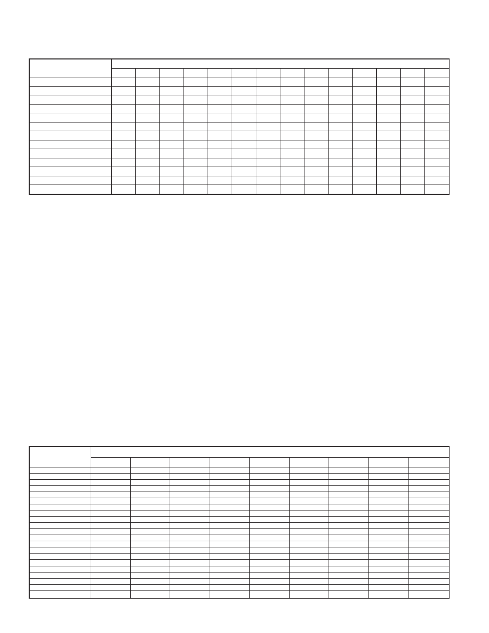
6. Refer to Table 4. Find outdoor temperature and evaporator
entering air wet-bulb temperature. At this intersection, note
superheat.
7. Refer to Table 5. Find superheat temperature located in item
6 and suction pressure. At this intersection, note suction line
temperature.
8. If unit has a higher suction line temperature than charted
temperature, add refrigerant until charted temperature is
reached.
9. If unit has a lower suction line temperature than charted
temperature, reclaim refrigerant until charted temperature is
reached.
10. When adding refrigerant, charge in liquid form into suction
service port using a flow-restricting device.
11. If outdoor air temperature or pressure at suction valve
changes, charge to new suction line temperature indicated
on chart.
XIII.
FINAL CHECKS
IMPORTANT:
Before leaving job, be sure to do the following:
1. Ensure that all wiring is routed away from tubing and sheet
metal edges to prevent rub-through or wire pinching.
2. Ensure that all wiring and tubing is secure in unit before
adding panels and covers. Securely fasten all panels and
covers.
3. Tighten service valve stem caps to 1/12-turn past finger
tight.
4. Leave User’s Manual with owner. Explain system operation
and periodic maintenance requirements outlined in manual.
5. Fill out Dealer Installation Checklist and place in customer
file.
CARE AND MAINTENANCE
For continuing high performance and to minimize possible equip-
ment failure, periodic maintenance must be performed on this
equipment.
Frequency of maintenance may vary depending upon geographic
areas, such as coastal applications. See Users Manual for informa-
tion.
TABLE 4—SUPERHEAT CHARGING
OUTDOOR TEMP (°F)
EVAPORATOR ENTERING AIR TEMPERATURE (°F WB)
50
52
54
56
58
60
62
64
66
68
70
72
74
76
55
9
12
14
17
20
23
26
29
32
35
37
40
42
45
60
7
10
12
15
18
21
24
27
30
33
35
38
40
43
65
—
6
10
13
16
19
21
24
27
30
33
36
38
41
70
—
—
7
10
13
16
19
21
24
27
30
33
36
39
75
—
—
—
6
9
12
15
18
21
24
28
31
34
37
80
—
—
—
—
5
8
12
15
18
21
25
28
31
35
85
—
—
—
—
—
—
8
11
15
19
22
26
30
33
90
—
—
—
—
—
—
5
9
13
16
20
24
27
31
95
—
—
—
—
—
—
—
6
10
14
18
22
25
29
100
—
—
—
—
—
—
—
—
8
12
15
20
23
27
105
—
—
—
—
—
—
—
—
5
9
13
17
22
26
110
—
—
—
—
—
—
—
—
—
6
11
15
20
25
115
—
—
—
—
—
—
—
—
—
—
8
14
18
23
Where a dash (—) appears, do not attempt to charge system under these conditions or refrigerant slugging may occur. Charge must be weighed in.
NOTE: Superheat °F is at low-side service port.
TABLE 5—REQUIRED SUCTION-LINE TEMPERATURE
SUPERHEAT
TEMP
(°F)
SUCTION PRESSURE AT SERVICE PORT (PSIG)
107.8
112.2
116.8
121.2
126.0
130.8
138.8
140.8
145.8
0
35
37
39
41
43
45
47
49
51
2
37
39
41
43
45
47
49
51
53
4
39
41
43
45
47
49
51
53
55
6
41
43
45
47
49
51
53
55
57
8
43
45
47
49
51
53
55
57
59
10
45
47
49
51
53
55
57
59
61
12
47
49
51
53
55
57
59
61
63
14
49
51
53
55
57
59
61
63
65
16
51
53
55
57
59
61
63
65
67
18
53
55
57
59
61
63
65
67
69
20
55
57
59
61
63
65
67
69
71
22
57
59
61
63
65
67
69
71
73
24
59
61
63
65
67
69
71
73
75
26
61
63
65
67
69
71
73
75
77
28
63
65
67
69
71
73
75
77
79
30
65
67
69
71
73
75
77
79
81
32
67
69
71
73
75
77
79
81
83
34
69
71
73
75
77
79
81
83
85
36
71
73
75
77
79
81
83
85
87
38
73
75
77
79
81
83
85
87
89
40
75
77
79
81
83
85
87
89
91
—8—