7 flow switch – Bosch AQ4 GWH 1600 P User Manual
Page 8
8
AQ4 Manual
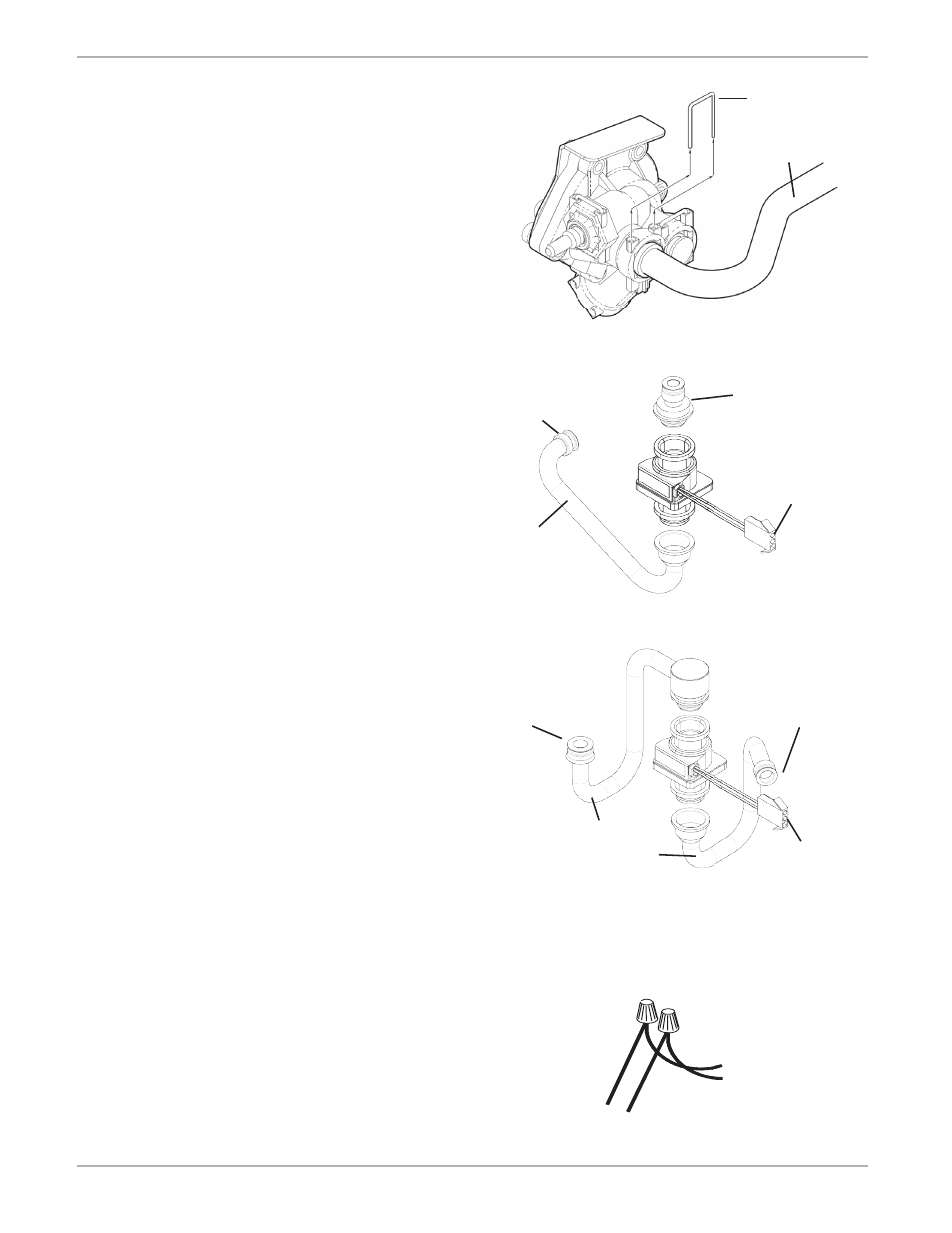
Fig. 8 Water valve pin
Water valve pin
AQ4 Installation instructions
2.7 Flow switch
Replacement piping and flow switch is included for
1600P/425PN and 1600H/425HN water heaters.
Check your model number on the right side of the
water heater cover to confirm which procedure to
follow.
2.7.1 Models 1600P/425PN
1. Shut off cold water supply isolation valve. If
none installed, install before proceeding. Open
hot water tap to relieve water pressure if water
is already connected.
2. Remove and save clip on lower right side of heat
exchanger.
3. Using a flat head screw driver remove and save
pin from front, right side of water valve. (Fig. 8)
4. Remove copper pipe and set aside.
5. Find and connect the black flow switch to the
bushing and pipes shown in Fig. 9A. Secure
together with supplied clips.
6. Position flow switch and connecting pipe and
bushing in place of the copper pipe that was
removed.
7. Reinstall pin in water valve and clip on heat
exchanger connection.
8. Connnect the three prong Molex connector cable
to the flow switch.
9. Connect control cable from vent motor to Molex
connector cable with wire nuts as seen in
Fig. 10.
2.7.2 Models 1600H/425HN
1. Shut off cold water supply isolation valve. If
none installed, install before proceeding. Open
hot water tap to relieve water pressure if water
is already connected.
2. Remove and save clip on lower right side of
hydrogenerator.
3. Remove and save pin from front, right side of
water valve using a flat head screwdriver.
(Fig. 8)
4. Remove copper pipe and set aside.
5. Find and connect the black flow switch to the
pipes shown in Fig. 9B.
Note:
There are two pipes included for connection
from flow switch to hydro-generator. One is
slightly longer than the other. If your water
heater’s serial number is greater than FD792, you
must use the longer pipe for this connection.
6. Position flow switch and connecting pipes in place
of the copper pipe that was removed. Secure
together with supplied clips.
7. Reinstall pin in water valve and clip on heat
exchanger.
8. Connnect the three prong Molex connector cable
to the flow switch.
9. Connect control cable to Molex connector cable
with wire nuts as seen in Fig. 10.
Fig. 10 Flow switch electrical connections
Connections from
Molex connector
cable (white and
yellow)
Connection from
vent motor (black
and red)
Fig. 9B 1600H/425HN flow switch connections
Connection to
water valve
Connection to
hydro generator
Flow switch
molex connector
Fig. 9A 1600P/425PN flow switch connections
Brass heat
exchanger
bushing
Connection to
water valve
Flow switch
molex connector
Replacement
pipe for pilot
models
Replacement
pipes for hydro
models
Pipe to heat
exchanger