English – AEG AR 4020 User Manual
Page 65
65
ENGLISH
NOTE
Check the content for completeness and visible dam-
►
age.
Should you notice any transport damage, please
►
contact your dealer immediately.
Disposal of Packaging Materials
The packaging protects the device from transport damage.
The packaging materials are selected in environmentally
friendly and disposal aspects and are recyclable.
Recycling of packaging materials saves raw
materials and reduces the waste. Dispose of
unwanted packag-ing in accordance with
local regulations.
NOTE
If possible, keep the original packaging for the dura-
►
tion of the warranty period, in order to be able to
properly package the device in the event of warranty
claims.
Connection
WARNING
During installation damages may occur!
Have the unit installed by a specialized workshop, if
►
possible.
Please observe all installation and connecting instruc-
►
tions for safe and trouble-free operation if installing
the unit yourself.
CAUTION
Wrong connections may damage the unit.
Use the ISO connectors when installing the unit.
►
Vehicle-specific ISO adapters are available at the
specialized car accessories trade, if necessary.
Rear Panel Connections
A
C B
D
E
A ISO connector B (speakers)
B Vehicle flat fuse (5 A)
C ISO connector A (power supply)
D LINE OUT:
RCA audio output L/R for amplifier
E Antenna connector
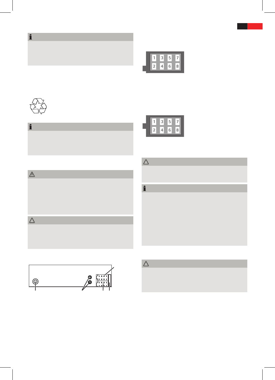
Configuration ISO Connectors
ISO connector A
1 Not connected
2 Not connected
3 Not connected
4 Continuous plus (memory)
5 Control voltage for electron-
ic/motor antenna or power
amplifier
6 Not connected
7 12 V (ACC)
8 GND
ISO connector B
1 Speaker rear right +
2 Speaker rear right -
3 Speaker front right +
4 Speaker front right -
5 Speaker front left +
6 Speaker front left -
7 Speaker rear left +
8 Speaker rear left -
CAUTION
Use speakers with an impedance of at least 4 Ohm.
►
The speaker cabling must be floating ground.
►
NOTE
For connecting the unit to two speakers only use only
►
front speaker cables.
Please observe that for the station memory connec-
►
tor 4 must be connected to continuous positive.
In some vehicle models the standard configuration
►
for connectors [4] and [7] (ISO A) is inverted. In this
case the station preset can get lost. To remedy invert
these connections 7 (ACC) and 4 (continuous posi-
tive).
Auto Antenna Power Supply A5 (ISO A)
CAUTION
Damage to the unit is possible!
Do not connect the terminal for antenna power to
►
the power supply of the antenna.
Max. load: 100 mA.
►
The terminal for antenna power is provided for a relay-
controlled antenna. The relay automatically extends the
antenna when the radio is turned on. The antenna retracts
again when the radio is turned off. This terminal can also
be used for an external amplifier. Please find details in the
amplifier’s manual.
Connect External Amplifier
Connect an external amplifier via LINE OUT. Please find
details in the amplifier’s manual.