Adt-lcd40 series electrical connections – ADT Security Services ADT-LCD40 User Manual
Page 21
ADT-LCD40 Series Electrical Connections
Power Connection
21
Document 50520 Rev D 7/25/00 P/N 50520:D
Section 4:
ADT-LCD40 Series Electrical
Connections
The ADT-LCD40 Series Annunciators can be powered by the Unimode
200 24VDC nominal power or from a remote UL listed, filtered power
supply such as the FCPS-24F. The power run to the annunciator must
be power-limited but need not contain a power supervision relay since
loss of power is inherently supervised through loss of communication
with the annunciator. Maximum ADT-LCD40 Series current draw from
the power supply (under alarm condition) is 66 mA. Maximum current
draw from the control panel's secondary power source (batteries) under
loss of AC power is 28 mA, since the LCD backlight is turned off during
AC loss. Backlighting is turned back on during AC loss only for alarm
conditions in the system.
1. All connections are power-limited and supervised
2. 12 - 18 AWG (0.75 - 3.25 mm
2
) wire for 24 VDC circuit is
acceptable
3. Power wire distance limitation is set by 1.2 volt maximum line
drop from source to end of circuit.
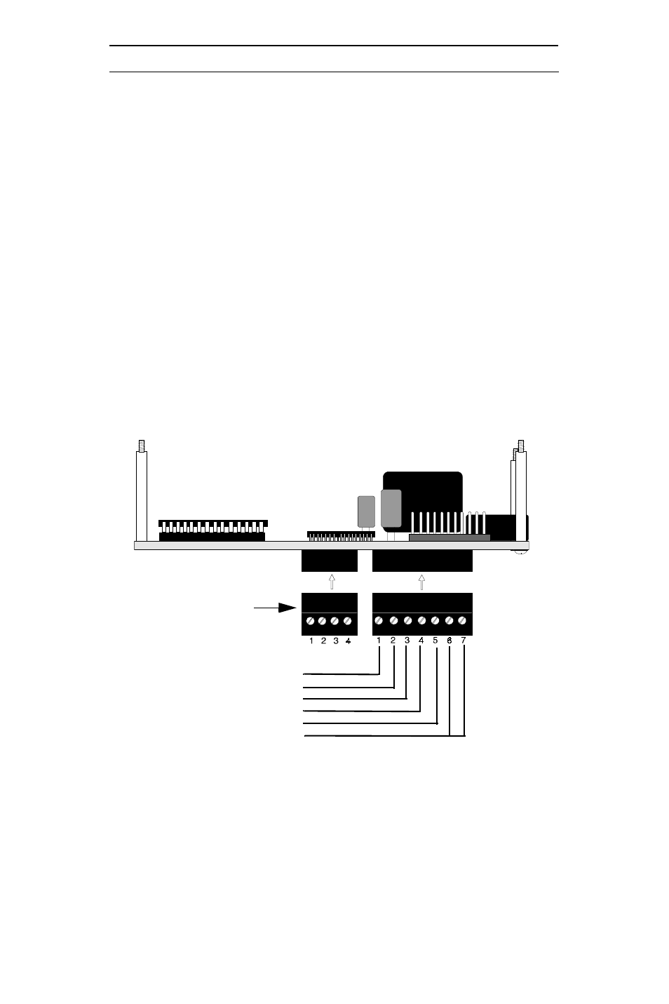
Figure 4-1: Power Connection
P1
P2
no connection
+24 VDC IN from main power supply
+24 VDC OUT to next ADT-LCD40(L)
-24 VDC IN from main power supply
-24 VDC OUT to next ADT-LCD40(L)
Earth Ground Option
ADT-LCD40 Series
Plug-in Terminal Blocks