Alamo RHINO SM72 User Manual
Sm72, Operator’s manual
© 2012 Alamo Group Inc.
SM72
Published 02/10
Part No. 00777511C
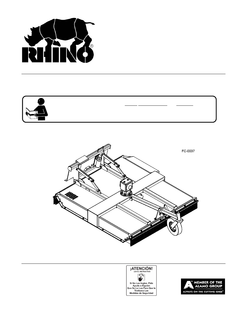
OPERATOR’S MANUAL
RHINO
®
1020 S. Sangamon Ave.
Gibson City, IL 60936
800-446-5158
Email: [email protected]
SKID STEER
ROTARY MOWER
This Operator's Manual is an integral part of the safe operation of this machine and must
be maintained with the unit at all times. READ, UNDERSTAND, and FOLLOW the Safety
and Operation Instructions contained in this manual before operating the equipment. C01-
Cover
$0.00
Table of contents
Document Outline
- SM72
- OPERATOR’S MANUAL
- To the Owner/Operator/Dealer
- Alamo Group Ag. Division is willing to provide
- one (1) AEM Mower Safety Practices Video
- TABLE OF CONTENTS
- Decal Location
- 1. 00725746 1 PELIGRO Translate Safety Material
- 2. 00776609 1 WARNING Max Cut
- 3. 00776609 1 DANGER Protect Operator
- 4. 00769737 1 DANGER Blades/Thrown Objects
- 5. 00777519 1 DANGER Multi Hazard
- 6. 00763977 1 INSTRUCT Notice to Owner
- 7. 02925100 1 INSTRUCT Genuine Alamo Parts
- 8. 02962764 2 DANGER Pinch Point
- 9. 00755742 1 DANGER Keep Away
- 10. 00756059 1 WARNING Warning Oil Leak
- 11. 00776608 1 DANGER Not a Step
- 12. 1 NAME SM72
- 13. 00757139 2 LOGO NAME Alamo Industrial Name
- 14. 00777521 1 DANGER SM72 Implement Weight
- 15. 03200347 1 REFLECT SMV Sign
- 16. 00776031 1 ________ Canister, Operations Manual
- 17. 31006H5C 3 ________ Bolt
- 18. 00024100 6 ________ Flatwasher
- 19. 02959924 3 ________ Locknut
- 20. 00777511C 1 ________ Manual, Operator’s SM72
- Decal Description
- Federal Laws and Regulations
- DEALER SETUP INSTRUCTIONS
- HITCH LINKAGE SETUP INSTRUCTIONS
- 1. Place the cutter on a solid level surface resting on its skids.
- 2. Cut away strapping material holding lower links on top of floating link.
- 3. Remove all hardware and bushings connected to lower transport link. Discard three-hole black transport link.
- 4. Attach two-hole lower link to deck and to middle hole on floating links, using existing hardware and bushings.
- 5. Place bushing between both arms above lower link and install bolt through bushing and fasten with locknut.
- 6. Repeat procedure on other link assembly.
- 7. Place bushing between both arms above mower link and install 5/8” bolt through bushing an fasten with 5/8” locknut.
- HITCH ASSEMBLY
- 1. Secure Hitch Weldment (1) to mower deck using 1" x 5" Bolts (7) and 1" Locknuts (6).
- 2. Insert Bushing (5) in upper holes of hitch weldment, place a set of Upper Floating Links (3) on each side of bushing, and secure together using 5/8” x 1-3/4” Bolt (8) and 5/8” Locknuts (9). Place bushing (5) between opposite upper floating l...
- 3. Place bushing (5) into end of Lower Floating Links (4) and secure between upper links with bolt (8) and locknut (9). Place another bushing into opposite lower link hole and place against outside of lugs near center of mower deck. Insert bolt (8) t...
- 4. Secure Safety Chain (2) around lower hitch frame.
- 5. Tighten all bolts and nuts to the recommended torque. (Refer to Image Asm-R-2070)
- FRONT CHAIN GUARD ASSEMBLY
- 1. Attach Front Chain Guard Bracket (4) to Front of Deck using 1/2” x 1-1/4” Bolts (1), 1/2” Flatwashers (2), and 1/2” Locknuts (3).
- 2. Attach the Right and Left Side Shields (5 and 6) to deck sides using bolts (1), flatwashers (2), and locknuts (3).
- 3. Tighten all bolts and nuts to the recommended torque. (Refer to Image Asm-R-0275)
- INSTALLING HYDRAULIC MOTOR
- 1. Elevate the rear of the unit approx. 2' to prevent oil from running out of gearbox
- 2. Remove gearbox shipping cover(00776159) and bolts and discard.
- 3. Replace gasket (2) with new gasket included in motor kit.
- 4. Verify that motor part number matches order.
- 5. Align Motor with return (Tank Port) facing discharge side of Mower
- 6. Hand thread four 1/2” x 1-1/2” grade 8 bolts and lockwashers into spindle.
- 7. Ensure that motor is fully seated and evenly tighten the four mounting bolts to 80ft. lbs.
- 8. Connect Hydraulic hoses to Motor Check to ensure hoses and motor are free of contamination.
- 9. With deck on a level surface check lubrication level in gearbox per dip stick.
- 10. Apply Decal (16) to mower deck for identification. (Refer to Figure Asm-R-0276)
- REAR CHAIN GUARD ASSEMBLY
- 1. Place Deflector Strap (6) against mower deck left side and Chain Guard Bracket (8) against mower deck right side. Place Rear Deflector Panel (5) against bracket and deflector and align hole through panel, deflector/bracket, and mower deck and secu...
- 2. Tighten all bolts and nuts to the recommended torque. (Refer to Image Asm-R-0272)
- SIDE DEFLECTOR ASSEMBLY
- SKID SHOE ASSEMBLY
- 1. Attach Flat Bar Left and Right Hand Skid Shoes (1 and 5) to the underside of the mower side skirts using 3/8” x 1-1/2” Bolts (2), Flatwashers (3), and Locknuts (4). Insert bolts from the underside up to ensure that threads do not become worn a...
- 2. Secure Front Right and Left Hand Skid Shoes (6 and 7, optional equipment) to the front of the mower using bolts (2), locknuts (4), and lockwashers (3). Front skid shoes have multiple hole patterns that enable deck height to be placed at desired mo...
- 3. Tighten all bolts and nuts to the recommended torque. (Refer to Image Asm-R-0274)
- OPTIONAL GAUGE WHEEL ASSEMBLY
- 1. Attach weldment. T/W Beam (1) to the mower with bolt (2) and Toplock nut (3)
- 2. Then attach tailwheel support RH and LH (4) to Bolt (5) with Toplock nut 6.
- 3. After attaching the tailwheel support attach them to position bracket (7) and attach with bolt (8) and toplock nut (9).
- 4. Finally attach the wheel (10) to the Tailwheel beam with the cotter pin (11) and Washer (12).
- 5. Tighten all bolts and nuts to the recommended torque. (Refer to Image Asm-R-0277)
- ASSEMBLY SECTION
- OPERATION SECTION
- RHINO SM72 SKID STEER ROTARY MOWER
- OPERATION INSTRUCTIONS
- 1. SM72 Standard Equipment and Specifications
- 2. OPERATOR REQUIREMENTS
- 3. GETTING ON AND OFF THE SKID STEER
- 4. STARTING THE SKID STEER
- 5. CONNECTING THE MOWER TO THE SKID STEER
- 5.1 Connecting the Hitches
- 1. Start the skid steer and tilt the hitch mounting plate forward while guiding the mounting plate crest under the attachment saddle of the mower. Raise and roll back the mounting plate until the mower hitch plate is securely seated flat against the ...
- 2. With the mower fully supported by the skid steer boom, lower the mower to ground level. Slightly tilt the front of the mower head upward about 2” from ground level. Turn off the engine, set the parking brake, and exit the skid steer. Push both l...
- 3. With the skid steer still completely shut down, secure the height limiting safety chain to the front of the skid steer chassis. Attach chain so that lift height is limited to 18 inches.
- 5.1 Connecting the Hitches
- 6. PRE-OPERATION INSPECTION AND SERVICE
- 7. OPERATING THE SKID STEER AND MOWER
- 8. DISCONNECTING THE MOWER FROM THE SKID STEER
- 1. Completely shut down the mower and skid steer and secure the skid steer in position by applying the parking brake. Wait for all movement to come to a complete stop before exiting the skid steer. Never extend any part of your body from the operator...
- 2. Disconnect the mower driveline from the skid steer. Lay the driveline down carefully to avoid damaging the driveline or its shield. Do not let the driveline fall into mud or dirt, which can contaminate the bearing and shorten the life of the drive...
- 3. Remove the height limiting safety chain from the front of the skid steer chassis.
- 4. Pull the latching handles upward to release the latch pins from the mower hitch tabs.
- 5. Board the skid steer, fasten your seatbelt, and start the engine. Tilt the mounting plate forward and back away from the mower at the same time. The mower should be released from the skid steer at this point.
- 9. MOWER STORAGE
- 1. Thoroughly clean all debris off the mower to prevent damage from rotting grass and standing water.
- 2. Lubricate all mower grease points and fill spindle oil level as detailed in the maintenance section.
- 3. Tighten all bolts and pins to the recommended torque.
- 4. Check the mower for worn and damaged parts. Perform repairs and make replacements immediately so that the mower will be ready for use at the start of the next season.
- 5. Store the mower in a clean, dry place with the mower housing resting securely on blocks or at ground level.
- 6. Keep the hydraulic hose ends from sitting in water, dirt and other contaminants. Connect the mower’s hydraulic lines together to prevent dirt and other contamination from entering the hydraulic system.
- 7. Use spray touch-up enamel where necessary to prevent rust and to maintain the appearance of the mower.
- 10. TRANSPORTING THE SKID STEER AND MOWER
- 11. TROUBLESHOOTING GUIDE
- trouble Possible Cause possible Remedy
- 2. Check to see if blades are Free Blades so they
- free swinging. swing.
- 3. Check for even wear on each Weigh Blades.
- blade tip. Were both blades Weight should be within 1 o
- changed at the same time? within 1 oz.
- Always replace
- both blades.
- 4. Blade broken. Replace blades, in set.
- 5. Blade carrier bent. Replace carrier.
- 6. Blade hub not properly Remove hub, check
- seated on shaft. tapered shaft, clean and replace.
- 7. New blade or bolts matched Replace blades or bolts
- with worn blade or bolts. in sets.
- 2. Carrier RPM too low. Hydraulic flow of mower motor
- power unit output are not compatible. See operation section of mower and
- skid steer for hydraulic specifications
- 3. Ground speed too fast. Reduce ground speed
- shifting to a lower gear.
- 4. Blades locked back. Free blades.
- 5. Blades riding up due to Replace blade bolts.
- blade bolt wear or loose bolts.
- 2. Improper type lubricant. Replace with proper lubricant.
- 3. Excessive trash build-up Remove trash.
- around the gear box.
- 4. Bearing or gears set up Consult your Dealer.
- improperly.
- 2. Worn Bearing. Replace bearing
- TROUBLE POSSIBLE CAUSE POSSIBLE REMEDY
- 2. Bent shaft. Replace oil seal and shaft.
- 3. Shaft rough in oil seal area. Replace or repair shaft.
- 4. Oil seal installed wrong. Replace seal.
- 5. Oil seal not sealing in the Replace seal or use a sealant on
- housing. OD of seal.
- 6. Oil level too high. Drain oil to proper level.
- 7. Sand hole in casting. Replace castings or gear box.
- 8. Gasket damaged. Replace gasket.
- 9. Bolts loose. Tighten bolts.
- cutting. Slow groundspeed of tractor but keep
- engine running at full PTO rpm. Cutting lower may help.
- 2. Dull blades. Sharpen or replace blades.
- 3. Height of cutter lower at See Cutting Height rear or front.
- Instructions.
- 2. Bolt hole elongated or Replace Bushing or
- oversized. Blade Carrier.
- 3. Locknut worn out. Replace Locknut.
- 2. Cutting in rocky conditions. Increase cutting height.
- MAINTENANCE SECTION
- LUBRICATION INFORMATION
- LUBRICATION SCHEDULE
- GEARBOX LUBRICATION
- BLADE SERVICING
- BLADE SHARPENING
- BLADE REMOVAL
- BLADE CARRIER INSPECTION
- BLADE CARRIER INSTALLATION
- STORAGE
- 1. Thoroughly clean the mower.
- 2. Lubricate the cutter as covered in Maintenance Section.
- 3. Tighten all bolts and pins to the recommended torque.
- 4. Check the mower for worn or damaged parts. Make replacements immediately.
- 5. Store the mower in a clean, dry place with the mower head resting on blocks.
- 6. Use spray touch-up enamel where necessary to prevent rust and maintain the appearance of the mower.
- STORAGE
- PROPER TORQUE FOR FASTENERS
- TO THE OWNER/OPERATOR/DEALER
- RHINO
- LIMITED WARRANTY
- 1. LIMITED WARRANTIES
- 1.01. Rhino warrants for one year from the purchase date to the original non-commercial, governmental, or municipal purchaser (“Purchaser”) and warrants for six months to the original commercial or industrial purchaser (“Purchaser”) that the ...
- 1.02. Manufacturer will replace for the Purchaser any part or parts found, upon examination at one of its factories, to be defective under normal use and service due to defects in material or workmanship.
- 1.03. This limited warranty does not apply to any part of the goods which has been subjected to improper or abnormal use, negligence, alteration, modification, or accident, damaged due to lack of maintenance or use of wrong fuel, oil, or lubricants, ...
- 1.04. Except as provided herein, no employee, agent, Dealer, or other person is authorized to give any warranties of any nature on behalf of Manufacturer.
- 2. REMEDIES AND PROCEDURES.
- 2.01. This limited warranty is not effective unless the Purchaser returns the Registration and Warranty Form to Manufacturer within 30 days of purchase.
- 2.02. Purchaser claims must be made in writing to the Authorized Dealer (“Dealer”) from whom Purchaser purchased the goods or an approved Authorized Dealer (“Dealer”) within 30 days after Purchaser learns of the facts on which the claim is based
- 2.03. Purchaser is responsible for returning the goods in question to the Dealer.
- 2.04. If after examining the goods and/or parts in question, Manufacturer finds them to be defective under normal use and service due to defects in material or workmanship, Manufacturer will:
- (a) Repair or replace the defective goods or part(s) or
- (b) Reimburse Purchaser for the cost of the part(s) and reasonable labor charges (as determined by Manufacturer) if Purchaser paid for the repair and/or replacement prior to the final determination of applicability of the warranty by Manufacturer.
- 2.05. Purchaser is responsible for any labor charges exceeding a reasonable amount as determined by Manufacturer and for returning the goods to the Dealer, whether or not the claim is approved. Purchaser is responsible for the transportation cost for...
- 3. LIMITATION OF LIABILITY.
- 3.01. MANUFACTURER DISCLAIMS ANY EXPRESS (EXCEPT AS SET FORTH HEREIN) AND IMPLIED WARRANTIES WITH RESPECT TO THE GOODS INCLUDING, BUT NOT LIMITED TO, MERCHANTABILITY AND FITNESS FOR A PARTICULAR PURPOSE.
- 3.02. MANUFACTURER MAKES NO WARRANTY AS TO THE DESIGN, CAPABILITY, CAPACITY, OR SUITABILITY FOR USE OF THE GOODS.
- 3.03. EXCEPT AS PROVIDED HEREIN, MANUFACTURER SHALL HAVE NO LIABILITY OR RESPONSIBILITY TO PURCHASER OR ANY OTHER PERSON OR ENTITY WITH RESPECT TO ANY LIABILITY, LOSS, OR DAMAGE CAUSED OR ALLEGED TO BE CAUSED DIRECTLY OR INDIRECTLY BY THE GOODS INCLU...
- 3.04. NO ACTION ARISING OUT OF ANY CLAIMED BREACH OF THIS WARRANTY OR TRANSACTIONS UNDER THIS WARRANTY MAY BE BROUGHT MORE THAN TWO (2) YEARS AFTER THE CAUSE OF ACTION HAS OCCURRED.
- 4. MISCELLANEOUS.
- 4.01. Proper Venue for any lawsuits arising from or related to this limited warranty shall be only in Guadalupe County, Texas.
- 4.02. Manufacturer may waive compliance with any of the terms of this limited warranty, but no waiver of any terms shall be deemed to be a waiver of any other term.
- 4.03. If any provision of this limited warranty shall violate any applicable law and is held to be unenforceable, then the invalidity of such provision shall not invalidate any other provisions herein.
- 4.04. Applicable law may provide rights and benefits to purchaser in addition to those provided herein.
- LIMITED WARRANTY
- Complete Ind Ag Mower Eng-Span Online10-10.pdf
- English Cover.pdf
- Page 1
- Complete Ind Ag Mower Spanish 10-10.pdf
- Spanish Cover.pdf
- Page 1
- Spanish Cover.pdf
- Complete Ind Ag Mower Spanish 10-10.pdf
- Spanish Cover.pdf
- Page 1
- Spanish Cover.pdf
- English Cover.pdf