AXIS 250S User’s Manual
Unit Connections
47
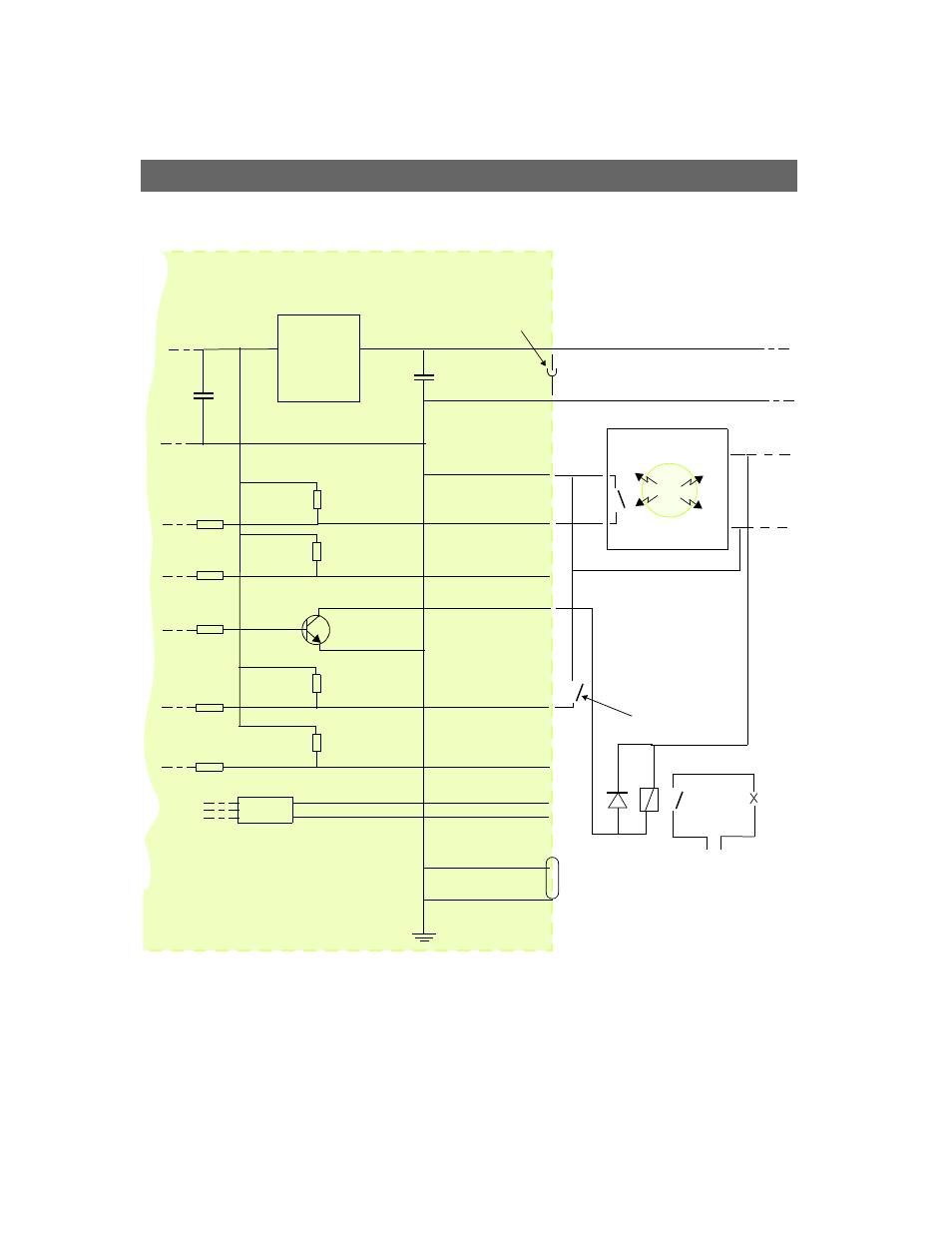
Schematic Diagram - Terminal Connectors A & B
o
o
Mode
Power
Supply
3.3V
!
!
!
!
!
o
Switch
A1
o
!
!
COM
!
GND PIN 5
o
!
!
o
o
Infrared Sensor
-
+
AXIS 250S
PS-K 9W
o
A2
o
o
!
!
o
A3
A4
!
!
!
!
!
!
o
B2
o
B1
o
B3
o
B4
RS-485
!
Device
o
o
o
o o
!
!
!
A
B
(e.g. door switch)
!
Center pin +
Ring -
External
power
supply
o
o
o
o
-
+
!
!