Ad620, Rev. e –12, Ad620a – Analog Devices AD620 User Manual
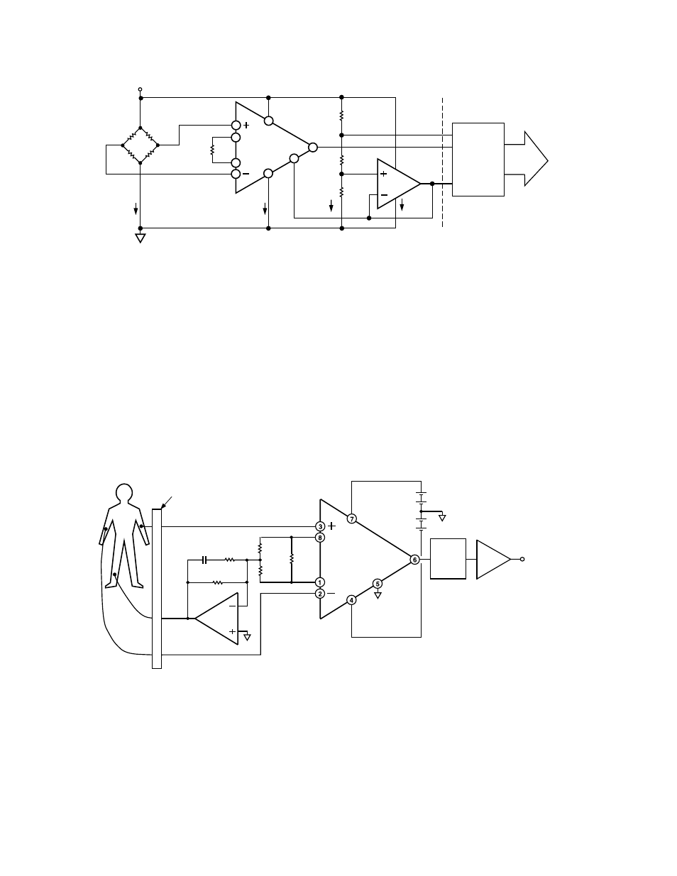
Page 12: Figure 36. a medical ecg monitor circuit
AD620
REV. E
–12–
3k
⍀
+5V
DIGITAL
DATA
OUTPUT
ADC
REF
IN
AGND
20k
⍀
10k
⍀
20k
⍀
AD620B
G=100
1.7mA
0.10mA
0.6mA
MAX
499
⍀
3k
⍀
3k
⍀
3k
⍀
2
1
8
3
7
6
5
4
1.3mA
MAX
AD705
Figure 35. A Pressure Monitor Circuit which Operates on a +5 V Single Supply
Pressure Measurement
Although useful in many bridge applications such as weigh
scales, the AD620 is especially suitable for higher resistance
pressure sensors powered at lower voltages where small size and
low power become more significant.
Figure 35 shows a 3 k
Ω
pressure transducer bridge powered
from +5 V. In such a circuit, the bridge consumes only 1.7 mA.
Adding the AD620 and a buffered voltage divider allows the
signal to be conditioned for only 3.8 mA of total supply current.
Small size and low cost make the AD620 especially attractive for
voltage output pressure transducers. Since it delivers low noise
and drift, it will also serve applications such as diagnostic non-
invasive blood pressure measurement.
Medical ECG
The low current noise of the AD620 allows its use in ECG
monitors (Figure 36) where high source resistances of 1 M
Ω
or
higher are not uncommon. The AD620’s low power, low supply
voltage requirements, and space-saving 8-lead mini-DIP and
SOIC package offerings make it an excellent choice for battery
powered data recorders.
Furthermore, the low bias currents and low current noise
coupled with the low voltage noise of the AD620 improve the
dynamic range for better performance.
The value of capacitor C1 is chosen to maintain stability of the
right leg drive loop. Proper safeguards, such as isolation, must
be added to this circuit to protect the patient from possible
harm.
G = 7
AD620A
0.03Hz
HIGH
PASS
FILTER
OUTPUT
1V/mV
+3V
–3V
R
G
8.25k
⍀
24.9k
⍀
24.9k
⍀
AD705J
G = 143
C1
1M
⍀
R4
10k
⍀
R1
R3
R2
OUTPUT
AMPLIFIER
PATIENT/CIRCUIT
PROTECTION/ISOLATION
Figure 36. A Medical ECG Monitor Circuit