ATEN CS-1708 User Manual
Page 16
CS-1708 / CS-1716 User Manual
8
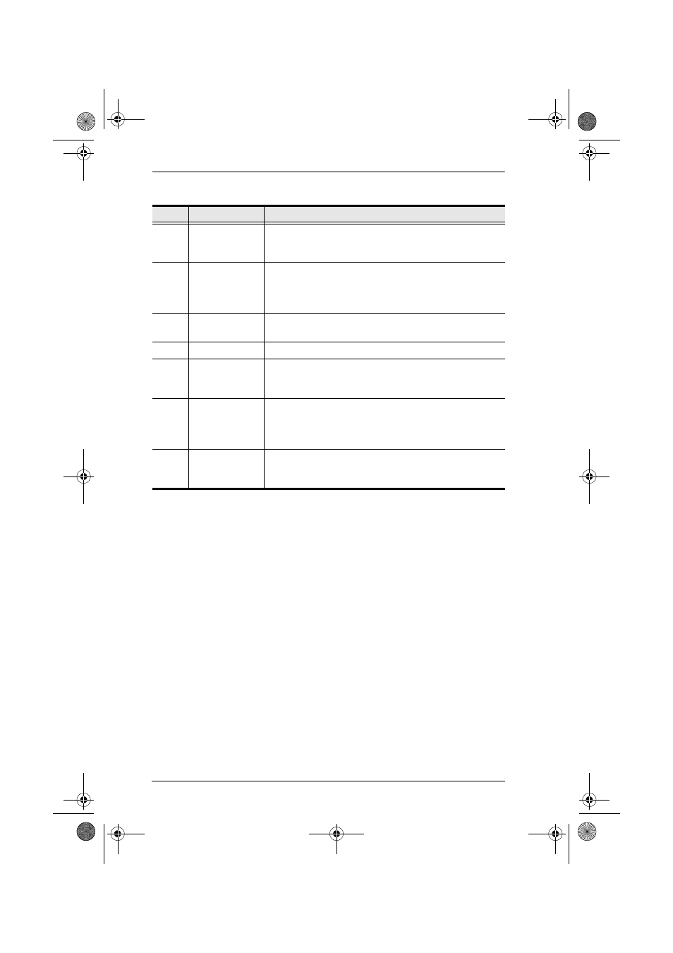
No.
Component
Description
1
Daisy Chain
Ports
When Daisy Chaining Units, the cables plug in here. The
port on the left is the Chain In port; the one on the right is
the Chain Out port.
2
KVM Port
Section
The cables that link to the computers plug in here. The
shape of these connectors has been specifically modified
so that only cables designed to work with this switch can
plug in (see the Cables section on page 4 for details).
3
Cable Tie Slot
If you want to use a cable tie to gather the cables together,
you can run it through this slot to attach it to the unit.
4
Power Jack
The power adapter cable plugs in here.
5
Firmware
Upgrade Port
The Firmware Upgrade Cable that transfers the firmware
upgrade data from the administrator's computer to the
switch (see page 37), plugs into this RJ-11 connector.
6
Firmware
Upgrade Reset
Switch
During normal operation and while performing a fimware
upgrade, this switch should be in the NORMAL position.
See Firmware Upgrade Recovery, page 42 for details
about the use of this switch.
7
Console Port
Section
If this is a Single Station installation, or if this is the First
Station unit of a daisy chained installation, your USB
keyboard, monitor, and USB mouse plug in here.
cs1708-1716.book Page 8 Thursday, July 19, 2007 3:06 PM