ADTRAN 1524ST Series User Manual
Page 2
Quick Start Guide, 61200560E1-13E, November 2006
Copyright © 2006 ADTRAN, All Rights Reserved
For more detailed documentation, visit us online at
Quick Start Guide
®
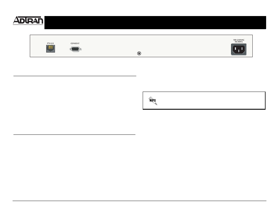
NetVanta 1524ST Series Switch
P/N 1200560E2/L2
E
THERNET
P
INOUTS
Pin
Name
Description
1
TR1+
Transmit/Receive 1 Positive
2
TR1-
Transmit/Receive 1 Negative
3
TR2+
Transmit/Receive 2 Positive
4
TR3+
Transmit/Receive 3 Positive
5
TR3-
Transmit/Receive 3 Negative
6
TR2-
Transmit/Receive 2 Negative
7
TR4+
Transmit/Receive 4 Positive
TR4-
Transmit/Receive 4 Negative
C
ONSOLE
P
INOUTS
Pin
Name
Description
1
DCD
Data Carrier Detect (output)
2
RD
Receive Data (output)
3
TD
Transmit Data (input)
4
DTR
Data Terminal Ready (input)
5
SG
Signal Ground
6
DSR
Data Set Ready (output)
7
—
Unused
8
CTS
Clear to Send (output)
9
—
Unused
C
ONFIGURE
Y
OUR
A
PPLICATION
More detailed documentation for configuring your ADTRAN unit is provided on the ADTRAN OS
System Documentation CD included in your shipment. For more detail on hardware setup, refer to
the appropriate NIM Quick Start Guides and the Hardware Installation Guide. For more detail on
configuring your system, refer to the ADTRAN Operating System (AOS) Command Reference
Guide, configuration guides, and technical support notes.
Important: For additional details on product features, specifications,
installation, and safety, refer to the appropriate Hardware Installation
Guide on the ADTRAN OS System Documentation CD shipped with the
base unit and available online at www.adtran.com.