Adsl link error indicator – Abocom AR1000 User Manual
Page 3
- 2 -
LED
Description
POWER
Router Power on/off Indicator
ADSL_PWR
ADSL Module Power on/off Indicator
ETH_LNK
Ethernet Link Indicator
ETH_ACT
Ethernet Active Indicator
ADSL_AUTO
ADSL Auto Connection Indicator
ADSL_LINK
ADSL Data Link Indicator
ADSL_ERR
ADSL Link Error Indicator
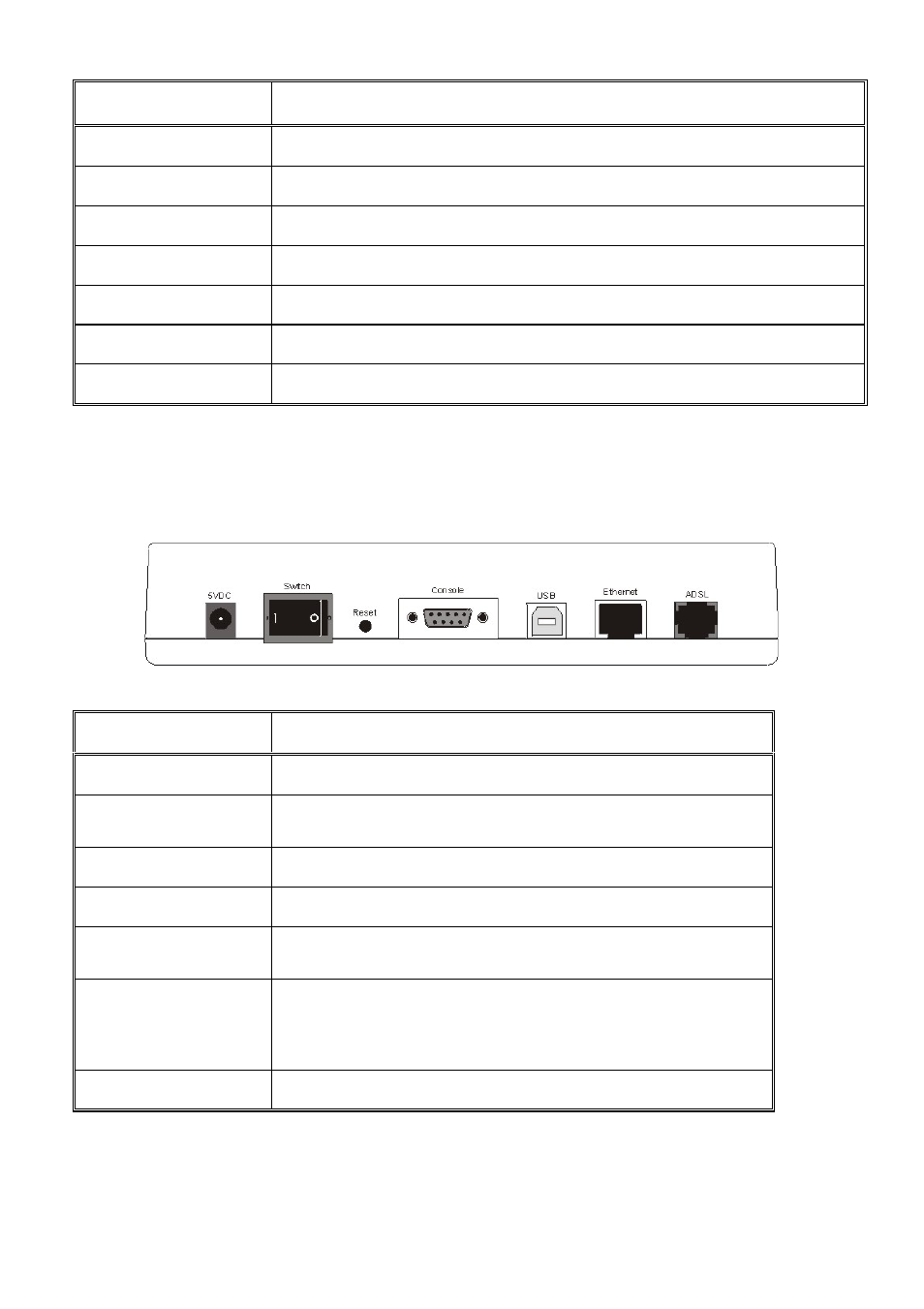
Connectors on the Rear Panel
The following table describes the function of the connectors and switches on the ADSL
ROUTER rear panel. See the following illustration for the location of the connectors
described in the following table.
Connectors on the rear panel
Connector Label
Connector Description
5VDC
5VDC Input Power Connector
Switch
POWER ON/OFF SWITCH
Reset
System Reset.
Console
Connects this device to the serial port on your PC.
USB
USB INPUT PORT
Ethernet
Connects to the Ethernet port on your PC using
the Non Hub Ethernet cable supplied with your
unit, or LAN hub using a straight-through cable.
ADSL
Connects this device to the wall jack.
- FM560MX (1 page)
- WU5204 (2 pages)
- WR201 (4 pages)
- UCM56CR (16 pages)
- WB1500H (1 page)
- FVR206 (10 pages)
- RE450MX (13 pages)
- X-Disk (1 page)
- Powerline Filter for PLC Communication PLF100 (2 pages)
- UTA128 (1 page)
- FSM612 (1 page)
- WUE1500 (20 pages)
- Internal Fax Modem 56K (19 pages)
- FE2000VX (11 pages)
- WMG2400 (3 pages)
- Wireless USB Adapter WUB1500 (1 page)
- WAP404 (2 pages)
- M73-APO07-300 (2 pages)
- UBT2K1H (2 pages)
- M73-APO0A-010 (15 pages)
- EFM56CC (1 page)
- FE1000SX (1 page)
- CWB1000 (19 pages)
- HomePlug 1.0 Turbo Ethernet Adapter PLE0085 (2 pages)
- UBT1000H (3 pages)
- CAS2047 (1 page)
- GFM560 (14 pages)
- FSM610 (1 page)
- UR3060E (2 pages)
- ECR500 (2 pages)
- FE2500MX (1 page)
- WBA580 (1 page)
- MC-56SVV (1 page)
- UBT3K (2 pages)
- PCMCIA (8 pages)
- 10/100M Fast Ethernet M73-APO08-420 (20 pages)
- AP900 (2 pages)
- UHL2000 (1 page)
- TA128 (1 page)
- VDSL to Ethernet Bridge VE1000 (1 page)
- ISDN TA PCI Card PI128 (1 page)
- Bluetooth Wireless USB Adapter UBT1000 (1 page)
- WB1500SH (1 page)
- ARM904 (3 pages)
- IAM800 (1 page)