1150 system board assembly and usb board – Lenovo E4325 User Manual
Page 70
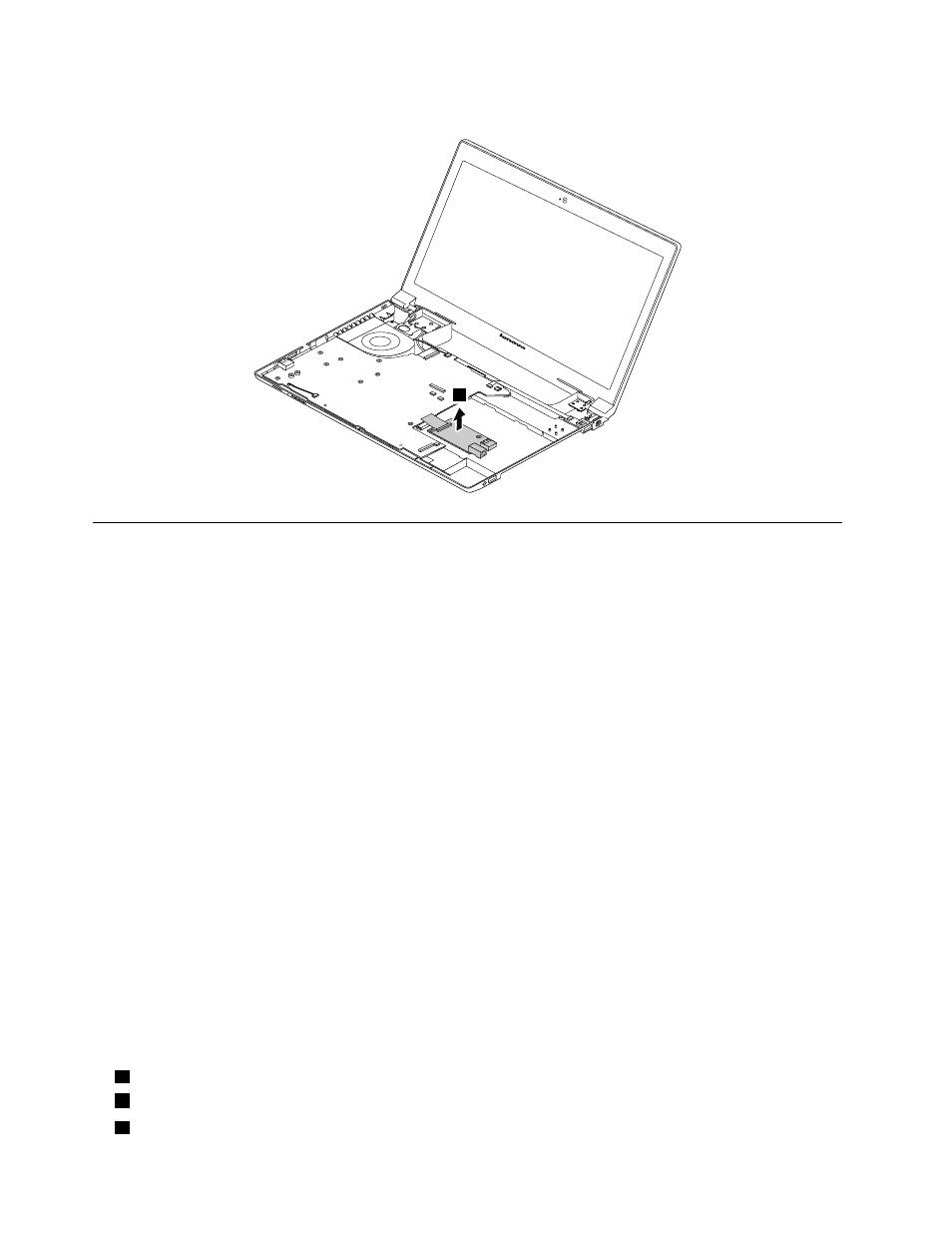
Remove the input/output (I/O) board.
4
1150 System board assembly and USB board
For access, remove these FRUs in order:
•
“1010 Battery pack” on page 50
•
“1020 Bottom slot cover” on page 50
•
“1030 Optical drive” on page 51
•
“1040 Memory module” on page 52
•
“1050 Hard disk drive assembly” on page 53
•
“1060 PCI Express Mini Card for wireless LAN” on page 55
•
“1080 Backup battery” on page 56
•
•
“1100 Keyboard bezel” on page 59
Important notice for replacing the system board
When replacing the system board, observe the following guidelines:
• Do not drop a system board on a bench top that has a hard surface, such as metal, wood, or composite.
• Do not apply any excessive force to a system board.
• Avoid rough handling of any kind.
• Avoid bending a system board or hard pushing to prevent cracking at each Ball Grid Array (BGA) chipset.
• When you put a system board down, be sure to put it only on a padded surface such as an ESD mat
or a corrugated conductive surface.
Locating major sensitive components on the system board
Attention: The following components mounted on a system board are extremely sensitive. Improper
handling of a system board can cause damage to the following components, and might cause a system
malfunction. When you service the system board, avoid any kind of rough handling.
a
Graphics chip (for discrete graphics models)
b
Microprocessor
c
Platform Controller Hub (PCH)
64
Hardware Maintenance Manual