1170 system board assembly – Lenovo K49 Notebook User Manual
Page 72
1170 System board assembly
Important notices for handling the system board:
When handling the system board, bear the following in mind:
• Be careful not to drop the system board on a bench top that has a hard surface, such as metal, wood, or composite.
• Avoid rough handling of any kind.
• At every point in the process, be sure not to drop or stack the system board.
• If you put a system board down, be sure to put it only on a padded surface such as an ESD mat or a corrugated
conductive surface.
For access, remove these FRUs in order:
•
“1010 Battery pack” on page 44
•
“1020 Bottom slot cover” on page 44
•
“1030 Optical drive or blank bezel” on page 45
•
“1040 Memory modules” on page 46
•
“1050 Hard disk drive assembly” on page 47
•
“1060 PCI Express Mini Card for wireless LAN” on page 49
•
“1070 mSATA solid-state drive (on some models)” on page 51
•
•
“1110 Keyboard bezel” on page 58
•
“1150 Backup battery” on page 63
•
“1160 Speaker assembly” on page 64
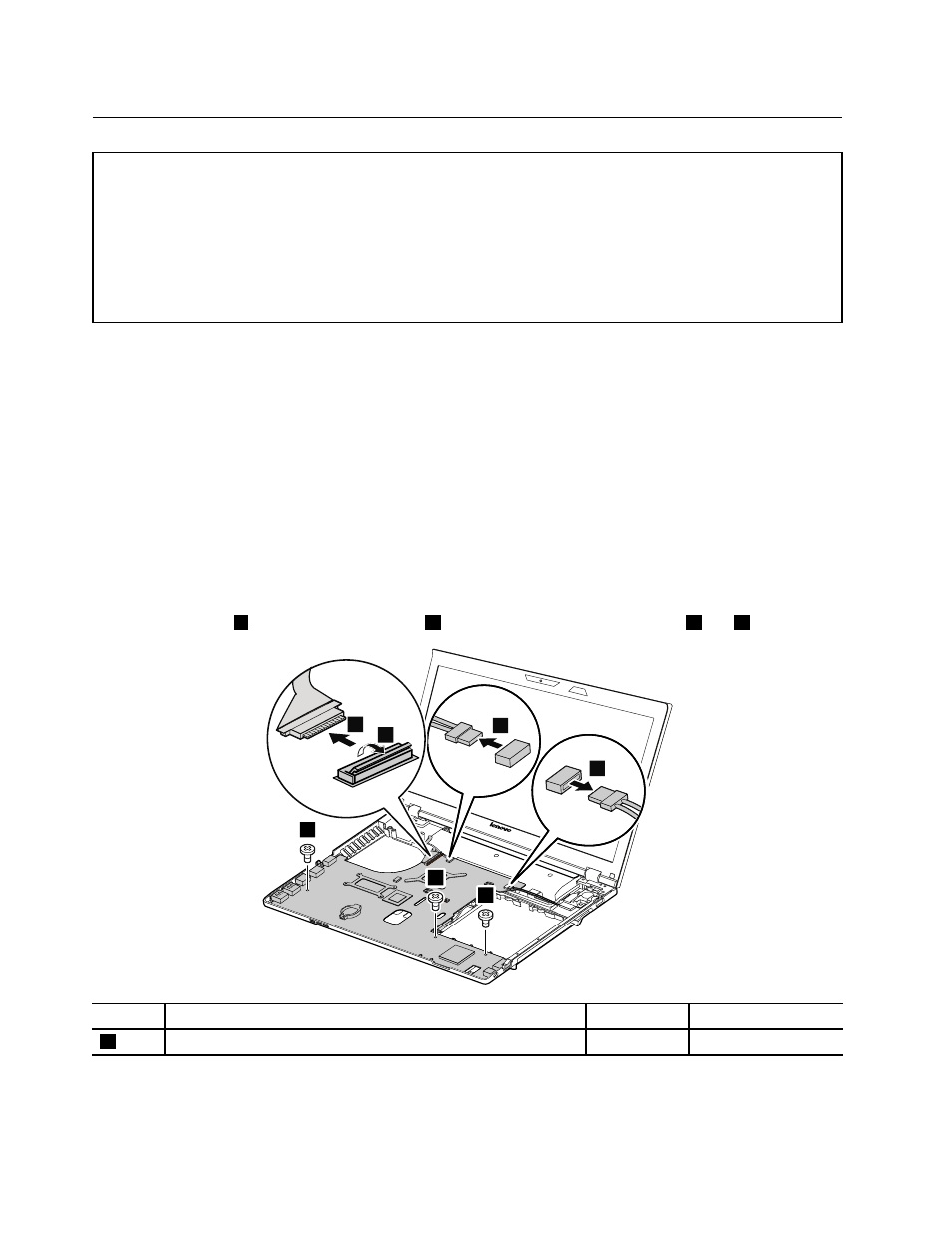
Removal steps of system board assembly
Remove the screws
1
. Then detach LCD cable
3
and speaker assembly connectors
4
and
5
.
4
5
2
3
1
1
1
Step
Screw (quantity)
Color
Torque
1
M2 × 3 mm, flat-head, nylon-coated (3)
Black
1.85 kgf-cm
66
Hardware Maintenance Manual