Lenovo Y50-70 User Manual
Page 63
59
Lenovo Y40-70/Y40-80/Y50-70/Y50-80/Y50-70 Touch/ Y50-80 Touch
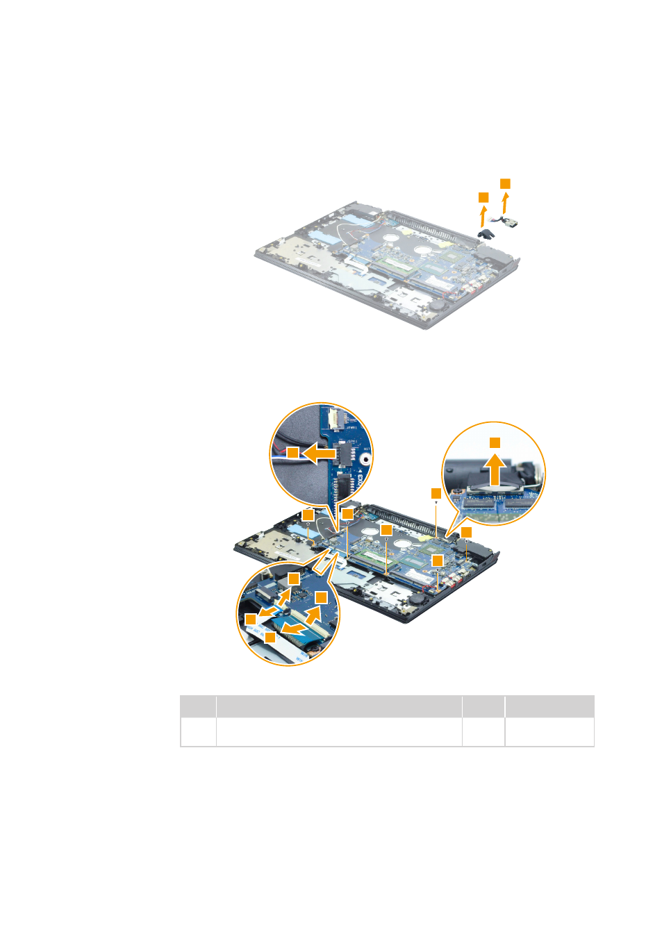
Figure 10. Removal steps of system board (continued)
Remove the RJ-45 door and DC-in jack in the direction shown by arrows 3.
Disconnect the connectors in the direction shown by arrows 4, 5 and 6.
Remove the screws 7.
Step Screw (quantity)
Color Torque
7
M2.0 × 3.0 mm, flat-head, nylok-coated (6)
M/B TO Logic UP (Y40-70/Y40-80)
Black 2.0 kgf*cm
When installing: Make sure that the connectors are attached firmly.
This manual is related to the following products: