Lenovo M5400 Touch Notebook User Manual
Page 58
54
Lenovo B5400/M5400/M5400 Touch Hardware Maintenance Manual
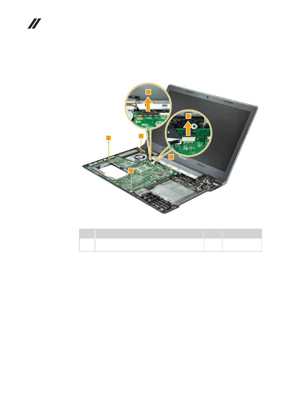
Figure 11. Removal steps of system board (continued)
Disconnect the two connectors in the direction shown by arrows
1
. Loosen the
screw
2
and remove the screws
3
.
Step Screw (quantity)
Color Torque
3
M2 × 4 mm, flat-head, nylok-coated (3)
MB to BASE & CRT BKT to MB to BASE
Black 1.85+/-0.15 kgf*cm
This manual is related to the following products:
See also other documents in the category Lenovo Notebooks:
- IdeaPad S10 (138 pages)
- IdeaPad S10 (7 pages)
- IdeaPad U455 (142 pages)
- IdeaPad Y550 (138 pages)
- IdeaPad Y550 (2 pages)
- IdeaPad S10-3s (81 pages)
- IdeaPad S10-3s (130 pages)
- IdeaPad S10-3s (2 pages)
- IdeaPad Y530 (152 pages)
- IdeaPad Y530 (2 pages)
- IdeaPad Y510 (77 pages)
- IdeaPad U450 (2 pages)
- IdeaPad U450 (142 pages)
- IdeaPad Y330 (148 pages)
- IdeaPad Y330 (2 pages)
- IdeaPad S10-2 (140 pages)
- IDEAPAD Y560P (145 pages)
- IdeaPad S10-3c (128 pages)
- IdeaPad S10-3c (88 pages)
- IdeaPad S10-3c (16 pages)
- IdeaPad S10-3c (4 pages)
- IdeaPad S10-3 FR (12 pages)
- IDEAPAD Y570 (15 pages)
- IDEAPAD Y570 (103 pages)
- IDEAPAD Y570 (51 pages)
- IdeaPad S100 (41 pages)
- IdeaPad S100 (79 pages)
- IdeaPad U450p (136 pages)
- IdeaPad U550 (2 pages)
- IdeaPad U550 (144 pages)
- IdeaPad U330 (2 pages)
- IdeaPad U330 (135 pages)
- IdeaPad S205 (46 pages)
- IdeaPad S205 (81 pages)
- IdeaPad S205 (10 pages)
- IdeaPad S205 (2 pages)
- 3000 G230 (140 pages)
- IdeaPad V360 (87 pages)
- IdeaPad V360 (58 pages)
- IdeaPad V360 (2 pages)
- IdeaPad U260 (77 pages)
- IdeaPad U260 (42 pages)
- IdeaPad U150 (140 pages)
- IdeaPad U460s (88 pages)
- IdeaPad U460s (143 pages)