Alamo PA92 User Manual
Pa92, Operator’s manual, Rear-mount boom mower
©2009 Alamo Group Inc.
$0.00
Published 03/09
Part No.
7192859C
OPERATOR’S MANUAL
ALAMO INDUSTRIAL
®
1502 E. Walnut
Seguin, Texas 78155
830-372-3551
Email: [email protected]
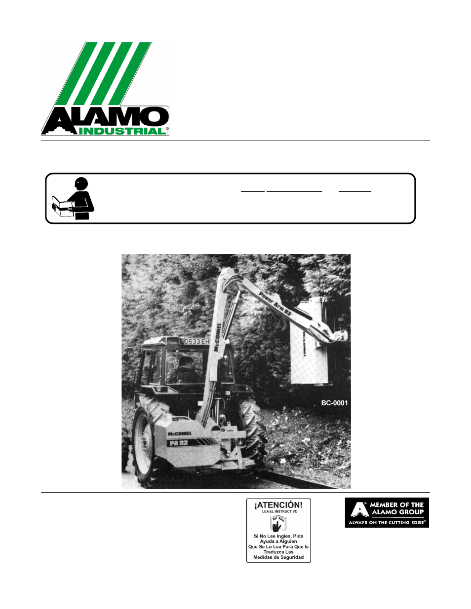
REAR-MOUNT
BOOM MOWER
This Operator's Manual is an integral part of the safe operation of this machine and must
be maintained with the unit at all times. READ, UNDERSTAND, and FOLLOW the Safety
and Operation Instructions contained in this manual before operating the equipment. C01-
Cover
PA92
Table of contents
Document Outline
- PA92
- OPERATOR’S MANUAL
- To the Owner/Operator/Dealer
- Alamo Industrial Division is willing to provide
- one (1) AEM Mower Safety Practices Video
- TABLE OF CONTENTS
- General Safety Instructions and Practices
- Operator Safety Instructions and Practices
- Equipment Operation Safety Instructions and Practices
- Connecting or Disconnecting Implement Safety Instructions and Practices
- Decal Location
- 1. 002369 1 DANGER Multiple Hazard Flail
- 2. 02958241 1 DANGER Multiple Hazard Boom
- 3. 02965262 1 DANGER Oil Leak/Penetration
- 4. 02965100 1 INSTRUCT Use Genuine Alamo Industrial Parts
- 5. 02962764 2 DANGER Pinch Points/Scissors
- 6. 02962765 1 DANGER Multiple Hazard/Crushing
- 7. 02965093 1 ATTENTION Do not over speed engine
- 8. 00763977 1 NOTICE Operator’s Manual Shipped with Equipment
- 9. 02977417 1 NOTICE Operator’s Manual Inside
- 10. 03200437 1 WARNING Pressurized Tank
- 11. 00769737 1 DANGER Keep Away Thrown Objects
- 12. 00756005 1 DANGER Rotating Driveline, Entanglement
- 13. 00756007 1 DANGER Use/Repair Shields & Guards
- 14. 00756485 1 DANGER Blades, Thrown Objects
- 15. 00756494 1 DANGER Driveline Hazards
- 16. 02958241 1 DANGER Boom Mower Multi-Hazard
- 17. 000678 3 INSTRUCT Grease Fitting Inside
- 18. 000108 1 INSTRUCT Flail Operating Instructions
- 19. 02966305 1 INSTRUCT Use Universal Hyd Oil
- 20. 1290030 1 INSTRUCT EP90 Oil in Speed Increaser
- 21. 00725746 1 PELIGRO Spanish Warning
- 22. D103 1 WARNING 540 PTO
- 23. 03200347 1 REFLECT SMV Sign
- 24. 1458392 2 REFLECT Red
- 25. 1458393 2 REFLECT Amber
- 26. 00773723 1 PELIGRO Rotating Driveline Translation
- 27. 02976881 1 INSTRUCT Mowing Safety Tips
- 28. 001651 2 LOGO NAME Alamo Industrial
- 29. 001650 1 LOGO Alamo Industrial
- 30. NFS 1 SER PLT Serial Plate
- 31. 7191852C 1 _________ PA91 Operator’s Manual
- 32. 02977046 1 _________ AEM Mower Safety Manual
- 33. 02153100 2 _________ Bolt
- 34. 00776031 1 _________ Operator’s Manual Canister
- 35. 10058000 1 _________ Bolt
- 36. 02919924 3 _________ Locknut
- 37. 00024100 3 _________ Flatwasher
- 38. 02982492 1 _________ Bracket, Canister
- Decal Description
- TRACTOR PREPARATION
- Fitting Operator Guard
- Wheel Width
- Ballast Weight
- JOHN DEERE CONVERSION KIT (81- 30- 059) for Si Models
- 1. A flow limiting valve manufactured by John Deere is available to provide an “open center” external supply. For further advice consult your John Deere dealer.
- 2. A control valve conversion kit (Part No. 81-30-059) consists of a relief valve blanking plug which should be installed in place of the existing relief valve and a pressure gallery blanking plug which is installed in place of the standard blanking ...
- DELIVERY
- 1. The machine is delivered in a partially dismantled condition. To make ready for attachment to the tractor it will be necessary to select a hard level surface
- 2. Cut the banding straps and remove the attached articles.
- 3. Fill the reservoir to capacity with oil selected from the chart on Section 3-9 to increase the stability of the machine.
- 4. Remove and discard the transport strap connecting the flail head to the frame and also the lift ram stop strapped to the rod.
- ATTACHMENT TO TRACTOR
- Si Model
- 1. Ensure the lift ram tap is fully open.
- 2. Adjust tractor drop arms to enable the draft links to lower within 15 ins (375 mm) of the ground.
- 3. Remove the top link and machine yoke completely.
- 4. Reverse the tractor squarely to the front of the machine, engage draft link pins and secure.
- 5. Attach yoke to the top hitch position on the tractor ensuring the lug for the top link is uppermost.
- 6. Unlimber the machine controls from its storage position and lift into the tractor cab.
- 7. Install the top link between yoke and upper hitch position on the machine. If necessary, fitting CAT I sleeves into the ball ends of the top link.
- *Measure the PTO drive shaft length as shown in diagram below and subtract 1 inch (25 mm.).
- 8. Lower the machine to the ground and fit the PTO shaft in position. Ensure that the collar locking devices on the PTO shaft are fully engaged. Wrap the torque chain around the tractor drawbar or any convenient point to prevent the shaft guard from ...
- 9. Raise the machine to working height.
- 10. Check that the rotor control valve is in the STOP position.
- 11. With PTO engaged on Ti model or with tractor external services activated on Si model, select “Lift Down”. This will level the frame and enable the lower yoke pins to be fitted. Select the hole which will, as near as possible position the PTO ...
- 12. Lower the quadrant lever so that the machines weight is taken by the yoke.
- 13. Adjust the top link to bring the pillar upright.
- 14. Carry out final adjustment of the tractor lift arm leveling box to bring the main frame horizontal. This should be checked with the arms at approximately half reach with the flail head clear of the ground.
- 15. Tighten up the check chains or adjustable stabilizers to hold the machine rigid without side-sway.
- 16. Remove the parking feet, turn inward 90 degrees and relocate in their housings.
- 17. Carefully operate the machine through its full range of movement while checking that the hoses are not strained, pinched, chaffed or kinked and that all movements are functioning correctly.
- 18. Fold the machine into the transport position.
- 19. The machine is now ready to proceed to the work site.
- Si Model
- FITTING CONTROL UNIT IN CAB
- OIL REQUIREMENTS
- RUNNING UP PROCEDURE
- PA92 Ti
- 1. Ensure that the rotor control is in “STOP” position, start the tractor, engage PTO and allow the oil to circulate for about 5 minutes before operating the arms.
- 2. Operate the armhead levers through their complete range ensuring that all movements are functioning correctly.
- 3. Check that the flail nuts and bolts are tight. Place the flail head at a safe position and move the rotor control to “ON” position. After initial fluctuation due to priming, the rotor should settle to a steady speed. Increase PTO speed to appr...
- 4. Check the hose runs and observe that they are free from any pinching, chafing, straining or kinks. Recheck the oil level in the tank and top up as necessary.
- PA92 Si
- 1. Ensure PTO lever is in neutral position, and isolate tractor hydraulic linkage. Start the tractor and select external service supply on the hydraulic controls. Allow the tractor to run for several minutes before attempting to operate any of the ma...
- 2. While operating, move the levers through their complete range ensuring that all movements are functioning correctly.
- 3. Check the tractor rear axle oil level and top up if necessary.
- 4. Place the flail head at a safe position and bring tractor engine revolutions to 1000 RPM to avoid stalling when the starting load is placed on the motor. Engage PTO and allow the rotor to run for several minutes. Do not leave the tractor cab or al...
- 5. After running up the machine, increase PTO speed to approximately 360 RPM. Run machine further for five minutes before disengaging the PTO and stopping tractor. The reason for this running period under a no load condition is to thoroughly circulat...
- 6. Check the hose runs and observe that they are free from any pinching, chafing, straining or kinks. Recheck the oil level in the tank and top up as necessary.
- PA92 Ti
- REMOVAL FROM TRACTOR
- 1. Select a firm level site for parking the machine.
- 2. Remove the parking feet, turn through 90 degrees and relocate in their housings.
- 3. Unscrew the lift ram tap and with the machine at approximately half reach in normal working position, i.e. not broken back. Operate the hydraulic services until the flail head roller is horizontal and level with the feet of the main frame.
- 4. Disengage tractor PTO and remove.
- 5. Disconnect stabilizers bars or loosen check chains as applicable.
- 6. Unbolt the control unit from the mounting pillar, remove from tractor cab and stow in a suitable location clear of the ground. On Si models only, the supply and return hoses must be disconnected from the tractor and stowed with their ends covered ...
- 7. Raise the machine on the tractor’s linkage to take the weight off the yoke and remove the lower yoke pins.
- 8. Lower the tractor draft links and place machine firmly on the ground.
- 9. Remove draft links and top link from the machine, drive tractor away and remove yoke. Blank off the end of the return hose with plug or small plastic bag if a self-seal coupling is not fitted.
- ASSEMBLY SECTION
- ALAMO INDUSTRIAL POWER ARM 92
- OPERATING INSTRUCTIONS
- 1. Standard Equipment and Specifications
- 3. TRACTOR REQUIREMENTS
- 6. Connecting Attaching Head to the Boom
- 8. OPERATING THE BOOM MOWER
- 8.1 Machine Controls
- 8.2 Arm Controls
- 8.3 Rotor Controls (Ti Only)
- 8.4 Engaging Drive
- Fully Independent Model
- 1. Ensure that the rotor control lever is moved to the “STOP” position before engaging the PTO shaft.
- 2. Allow the oil to circulate for a minute or so before operating the armhead levers.
- 3. Position the flail head in a safe position, increase the engine speed to a high idle and move rotor control lever to “ON”.
- 4. After initial surging the rotor will run at an even speed. Starting the rotor this way reduces the starting loads imposed on the hydraulic motor and the drive splines.
- Tractor Supply Model
- 8.5 Rotor Operating Speed
- 8.6 Forward Speed
- 8.7 Tractor Position
- 8.8 Operating Speed
- 8.9 Working Close In and High
- Fully Independent Model
- 8.10 Breakaway Action
- 8.16 Grass Cutting
- 9. DRIVING THE TRACTOR AND IMPLEMENT
- 10. OPERATING THE TRACTOR AND IMPLEMENT
- 11. OPERATING INSTRUCTIONS
- 1. Engage the PTO shaft at low engine RPM and speed the engine up after blades are fully engaged. Never engage the PTO shaft at a high engine RPM. This could cause damage to the PTO shaft as well as the Speed Increaser and Pump. Always operate PTO at...
- 2. Proper ground speed for cutting will depend upon the height, type, and density of material to be cut. Normally, ground speed will range from 2 to 5 m.p.h. Tall dense material should be cut at low speed while thin medium height material can be cut ...
- 3. Always run the Mower at the highest position which will enable you to obtain the desired cutting results. Allowing the blades to cut into the ground will cause wear and undue strain on the mower frame and mower components.
- 11.1 Foreign Debris Hazards
- 11.2 Bystanders/Passersby Precautions
- 11.3 Engaging the Power Take Off (PTO)
- 11.4 Operating Speed and Ground Speed
- 11.5 Operating the Mower
- 11.6 Operating the Attached Mower Heads
- 12. TRACTOR, BOOM, AND ATTACHED HEAD STORAGE
- 13. DISCONNECTING THE MOWER
- 14. TRANSPORTING THE TRACTOR AND IMPLEMENT
- 15. TROUBLESHOOTING GUIDE
- TROUBLE POSSIBLE CAUSE POSSIBLE REMEDY
- TROUBLE POSSIBLE CAUSE POSSIBLE REMEDY
- TROUBLE POSSIBLE CAUSE POSSIBLE REMEDY
- LUBRICATION
- 1. Power take-off shaft - The PTO shaft should be regularly examined to ensure that it is in good condition together with the guards. The universal joints should be greased very sparingly, i.e., one shot a week.
- 2. The two halves of the plastic guard should be checked daily to ensure that they can spin freely on the shaft. The nylon slip rings which support the guard on the drive shaft should be lightly greased at weekly intervals.
- 3. The telescoping drive shaft should be similarly separated and grease applied to the internal shaft at approximately 100 hour intervals.
- HYDRAULIC SYSTEM
- Oil Supply
- Filtration Maintenance
- HYDRAULIC HOSES
- Hose Replacement
- 1. Replace one hose at a time to avoid the risk of wrong connections.
- 2. When the hose is screwed to an additional fitting or union, use a second spanner on the union to avoid breaking both seals.
- 3. Do not use jointing compound on the threads.
- 4. Avoid twisting the hose. Adjust the hose line to ensure freedom from rubbing or trapping before tightening hose end connections.
- Hose Warranty
- Hose Replacement
- P.T.O. GEARBOX
- FLAILHEAD
- 1. Frequently inspect the rotor assembly for damaged or missing flails. Bolts and nuts securing the flails to the rotor should be regularly checked and kept tight. The correct torque setting for these locknuts is 135 Nm (100 lbs/ft.). Use only the co...
- 2. Do not attempt to run the rotor with flails missing. Imbalance will cause severe vibration and can rapidly damage the rotor shaft bearings. As an emergency measure, if a flail is broken off or lost, remove another on the opposite site of the rotor...
- 3. Blunt flails absorb a lot of power and leave an untidy finish to work. They should be sharpened on a grindstone or with a portable grinder periodically.
- 4. Wear protective gear when sharpening flails.
- 5. Ensure that the bearing housings and hydraulic mounting nuts and bolts are kept tight. They should be checked during servicing.
- CABLES
- HOSE CONNECTIONS
- TO THE OWNER/OPERATOR/DEALER
- ALAMO-INDUSTRIAL
- LIMITED WARRANTY
- 1. LIMITED WARRANTIES
- 1.01. Alamo Industrial warrants for one year from the purchase date to the original non-commercial, governmental, or municipal purchaser (“Purchaser”) and warrants for six months to the original commercial or industrial purchaser
- 1.02. Manufacturer will replace for the Purchaser any part or parts found, upon examination at one of its factories, to be defective under normal use and service due to defects in material or workmanship.
- 1.03. This limited warranty does not apply to any part of the goods which has been subjected to improper or abnormal use, negligence, alteration, modification, or accident, damaged due to lack of maintenance or use of wrong fuel, oil, or lubricants, ...
- 1.04. Except as provided herein, no employee, agent, Dealer, or other person is authorized to give any warranties of any nature on behalf of Manufacturer.
- 2. REMEDIES AND PROCEDURES.
- 2.01. This limited warranty is not effective unless the Purchaser returns the Registration and Warranty Form to Manufacturer within 30 days of purchase.
- 2.02. Purchaser claims must be made in writing to the Authorized Dealer (“Dealer”) from whom Purchaser purchased the goods or an approved Authorized Dealer (“Dealer”) within 30 days after Purchaser learns of the facts on which the claim is based
- 2.03. Purchaser is responsible for returning the goods in question to the Dealer.
- 2.04. If after examining the goods and/or parts in question, Manufacturer finds them to be defective under normal use and service due to defects in material or workmanship, Manufacturer will:
- (a) Repair or replace the defective goods or part(s) or
- (b) Reimburse Purchaser for the cost of the part(s) and reasonable labor charges (as determined by Manufacturer) if Purchaser paid for the repair and/or replacement prior to the final determination of applicability of the warranty by Manufacturer.
- 2.05. Purchaser is responsible for any labor charges exceeding a reasonable amount as determined by Manufacturer and for returning the goods to the Dealer, whether or not the claim is approved. Purchaser is responsible for the transportation cost for...
- 3. LIMITATION OF LIABILITY.
- 3.01. MANUFACTURER DISCLAIMS ANY EXPRESS (EXCEPT AS SET FORTH HEREIN) AND IMPLIED WARRANTIES WITH RESPECT TO THE GOODS INCLUDING, BUT NOT LIMITED TO, MERCHANTABILITY AND FITNESS FOR A PARTICULAR PURPOSE.
- 3.02. MANUFACTURER MAKES NO WARRANTY AS TO THE DESIGN, CAPABILITY, CAPACITY, OR SUITABILITY FOR USE OF THE GOODS.
- 3.03. EXCEPT AS PROVIDED HEREIN, MANUFACTURER SHALL HAVE NO LIABILITY OR RESPONSIBILITY TO PURCHASER OR ANY OTHER PERSON OR ENTITY WITH RESPECT TO ANY LIABILITY, LOSS, OR DAMAGE CAUSED OR ALLEGED TO BE CAUSED DIRECTLY OR INDIRECTLY BY THE GOODS INCLU...
- 3.04. NO ACTION ARISING OUT OF ANY CLAIMED BREACH OF THIS WARRANTY OR TRANSACTIONS UNDER THIS WARRANTY MAY BE BROUGHT MORE THAN TWO (2) YEARS AFTER THE CAUSE OF ACTION HAS OCCURRED.
- 4. MISCELLANEOUS.
- 4.01. Proper Venue for any lawsuits arising from or related to this limited warranty shall be only in Guadalupe County, Texas.
- 4.02. Manufacturer may waive compliance with any of the terms of this limited warranty, but no waiver of any terms shall be deemed to be a waiver of any other term.
- 4.03. If any provision of this limited warranty shall violate any applicable law and is held to be unenforceable, then the invalidity of such provision shall not invalidate any other provisions herein.
- 4.04. Applicable law may provide rights and benefits to purchaser in addition to those provided herein.