Installing your pnp300/350, Operation, 1 operating the pop-up panel – Altinex Pop `N Plug PNP350 User Manual
Page 10: Tabletop solutions
TABLETOP SOLUTIONS
400-0114-004
9
INSTALLING YOUR PNP300/350
6
Step 1. Cut an opening into the table’s surface.
Refer to the ALTINEX website at
for the cutout
requirements.
Note: The table can be 0.25 in (6 mm) to
3.75 in (95 mm) thick. Always confirm
dimensions before cutting to ensure that
specifications have not changed.
Step 2. Place the support brackets under the
table and place them between the support
mount grooves on the side of the
PNP300/350 unit. Attach the brackets to
the groove at the desired height and
secure them to the bottom of the table
using the setscrew. There are two support
brackets, one for each side of the unit.
See DIAGRAM 3 for details.
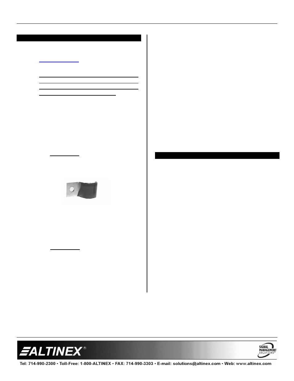
Step 3. Secure the cables by using the provided
cable clamps of the type shown below.
Step 4. Pass the power cord from the bottom of
the housing and attach it to the bottom of
the table using the cable clamp and screw
supplied with the PNP300/350. Do not
clamp the cord too tight or too loose.
See DIAGRAM 4 for an example of cable
mounting the cables.
Step 5. Connect the appropriate cables with the
correct input connectors on the bottom of
the unit. The following standard
connections are provided:
PNP300:
AC power cable
= AC power
Black RCA cable
= audio left
Red RCA cable
= audio right
Yellow RCA cable
= composite video
Black DB-15 HD
= computer video
DB-9 cable
= serial data
Red RJ-45 cable
= network
Silver RJ-11 cable
= telephone/modem
A round gray cable is also provided for
connection to a stereo audio line.
PNP350:
AC power cable (2)
= AC power
Red RJ-45 cables (6) = for independent
network connections
OPERATION
7
7.1 OPERATING THE POP-UP PANEL
To raise the unit, push down on the center of the
top cover of the PNP300/350 until a click is heard
and then let go. The connector panel will pop up to
allow access to the connectors.
To lower the unit, disconnect all cables on the front
connector panel. Then push down on the center of
the top cover until the latch engages and the unit is
locked in place.