Vollrath U431 Water Cooled User Manual
Page 22
16
4.3
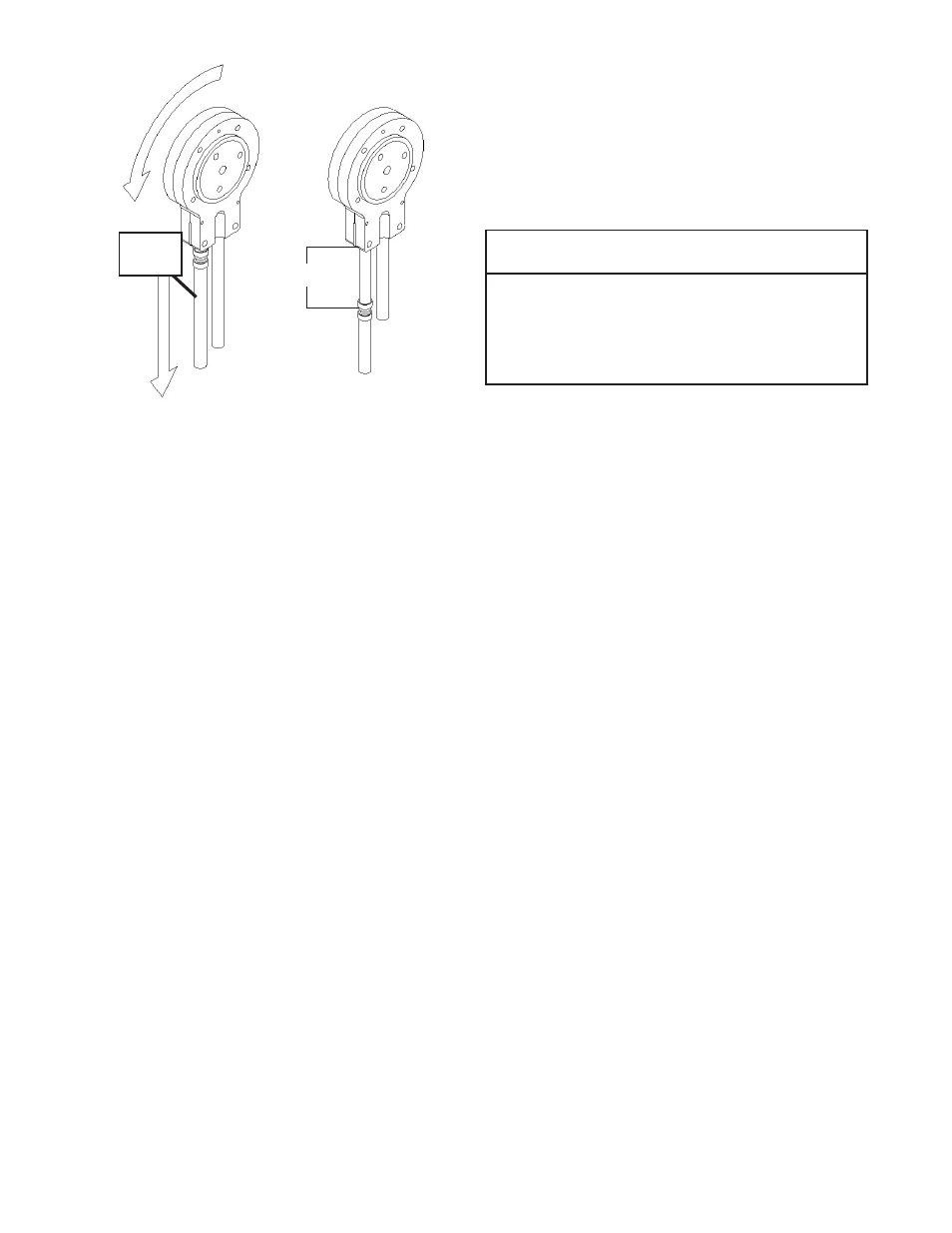
MIX PUMP HOSE REPLACEMENT
Mix pump hose must be replaced when tubing cannot be
further repositioned (every four to eight weeks). Failure
to comply will result in hose failure and possible pump
damage. Follow the steps below to replace the hose:
A.
Run cleaning solution through pump.
B.
Turn the pump off and relieve any pressure by
opening the spigot.
C.
Disconnect the mix pump hose at each end.
D.
Grasp the discharge hose end with one hand and
turn the pump on. Pull down on the hose until all
of the remaining hose is removed from the pump.
Turn pump off.
E.
Rotate pump roller assembly so one roller is at
the 6:00 position.
F.
Use a brush that fi ts in the opening and clean the
pump roller assembly, fi rst with detergent water
and then clear water.
G.
Connect the new mix pump hose to the pickup
hose adapter using the small clamp.
H.
Feed one end of the mix pump hose into the
pickup hose side (left) of the black cover.
NOTE
Feed the tube into the clamp so the natural curve of
the tube is towards the outside of the black cover.
This prevents the hose from looping around the
black cover twice.
I.
Gently push the hose into the black cover until it
begins to feed.
J.
Allow the hose to feed itself through the pump
until about 6" (15cm) remains on the entering
side and turn the pump off.
L.
Connect the mix pump hose to the elbow fi tting
(located on the left side of the mix line manifold)
using a small hose clamp. Be careful not to twist
the mix hose.
M.
Turn the pump on.
N.
Allow the remaining 6" (15cm) of tubing to feed
through the pump until the hose adapter prevents
further feeding and turn the pump off.
CAUTION
Risk of Product Damage
Air/Mix Tee must remain below the black cover
clamp. If the Tee is above the pump, the mix may
drain into the air compressor, resulting in pump
damage.
P.
Connect the free end of the mix pump hose to the
3-way Tee. When all connections are complete,
the 3-way Tee must be lower than the black pump
housing.
Q.
The pump is now ready to sanitize.
NOTE
The hose timer must be reset each time the hose is
repositioned or replaced to keep an accurate record
of the hose service time. Refer to Section 4.7 I for
instrcutions on resetting the timer.
4.4
DRIVE BELT TENSION ADJUSTMENT
To check belt tension, follow the steps below:
A.
Remove a side panel and the back panel.
B.
Use a Burroughs Belt Tension Gauge to set the
tension for the drive belt. Set the belt tension to
55-60 lbs.
C.
If an adjustment is necessary, loosen the four
motor plate retaining nuts, adjust belt tension
then retighten the four nuts.
D.
Using a straightedge, check that the drive motor
pulley is aligned with the speed reducer pulley.
Align the pulley if necessary.
NOTE
Belt life will be increased if new drive belts are
tightened after two or three weeks of operation.
Figure 4-2 Pump Hose Reposition
Pickup
End
12” to 14”