Pfannenberg DTS 3000 Series User Manual
Page 9
6
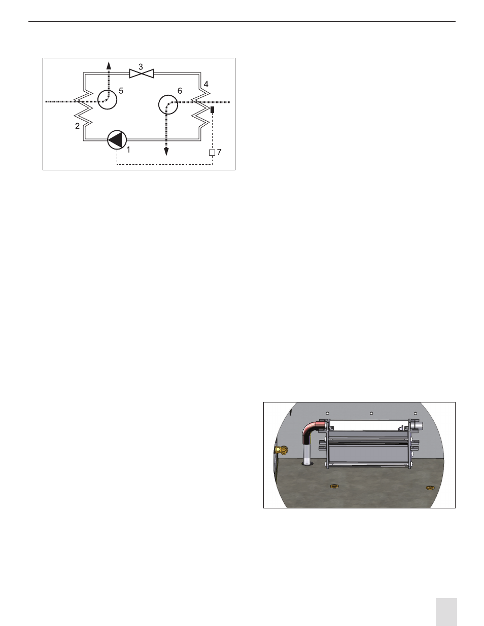
5.2 Theory of Operation
∞
∞
1 Compressor
2 Heat exchanger (condenser)
3 Expansion valve/ capillary line
4 Heat exchanger (evaporator)
5 fan, exterior circulation
6 fan, inner circulation
7 Electronic control system with temperature sensor
The compressor (1) compresses the refrigerant
until it becomes a high pressure gas. During the
compression process, the temperature of the
refrigerant gas increases.
As the refrigerant in the form of a high pressure, high
temperature gas flows through the condenser (2)
the refrigerant cools and condenses as the heat is
dissipated to the ambient (outside of the electrical
panel) air.
This is accomplished by the condenser fan (5) pulling
in ambient air into the housing and then pushes
the ambient air through the fin and coils of the
condenser (2) and back out of the housing and into
the ambient environment at a higher temperature.
As the now liquid refrigerant passes through the
expansion valve (3) the pressure drops and the
refrigerant becomes a liquid / gas mixture.
As the refrigerant in the form of a liquid / gas passes
through the evaporator (4) it absorbs the heat
from air in the electrical panel enclosure while also
dehumidifying it.
This process lowers the temperature of the air in the
electrical panel enclosure
This is accomplished by the evaporator fan (6)
pulling in the hot air from the electrical panel
enclosure and pushes it through the evaporator
(4) and back into the electrical panel enclosure at a
lower temperature.
The cooling unit is electronically controlled. To
accomplish this a temperature sensor monitors the
temperature inside the electrical panel enclosure
and regulates the function of the cooling unit.
The refrigerants used in the cooling unit are non-
combustible and are minimally detrimental to the
atmosphere.
5.3 Condensation Consideration
During operation, the moisture in the air inside of
the electrical panel enclosure condenses on the fins
of the evaporator and is collected as condensate.
In order to avoid any damage to the electrical
panel enclosure contents or to the cooling unit, the
condensate must be removed from the cooling unit.
The condensate is removed as follows: The
condensate drains into a condensate tray located
at the bottom of the cooling unit and is evaporated
into the ambient air by means of an electrical
heating element.
The free discharge of any accumulated condensate
must be provided for to ensure trouble-free
operation of the cooling unit.
The PTC-heater starts heating immediately on the
application of power to the cooling unit. The PTC-
heater is self-controlled and it’s temperature will
vary depending on the level of condensate in the
condensate tray.