Warning – Pfannenberg DTS 3000 Series User Manual
Page 11
8
6.3 Test Mode / Start-up
The start-up / test mode is activated whenever
the unit has had power removed and re-applied.
While in this mode the cooling unit operates
independently from the ambient conditions when
the door contact is closed.
The cooling unit runs through a start up sequence
that takes approximately 30 seconds to accomplish.
The start-up mode is also activated whenever the
door limit switch is closed.
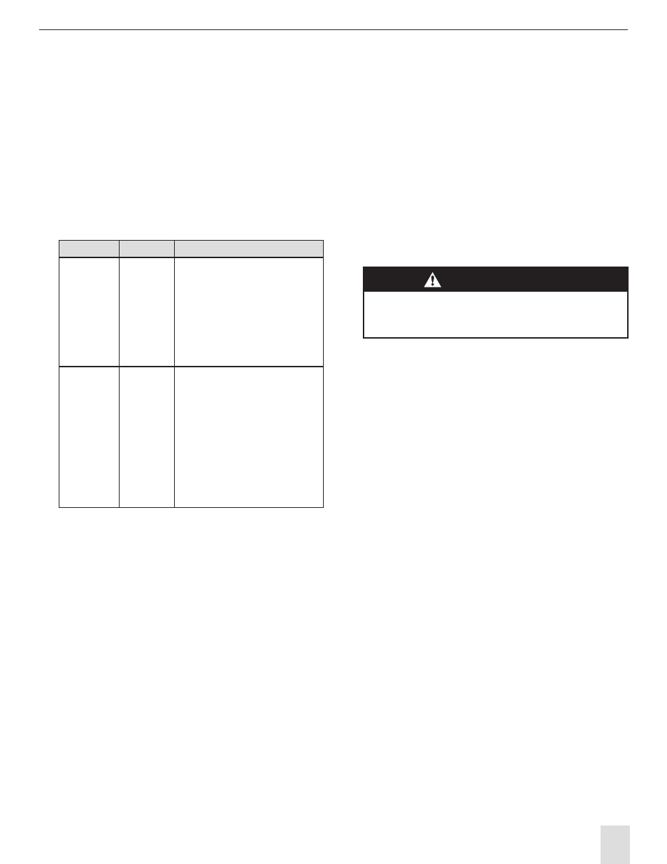
Modus
Time Curve
Characteristics
Start-up
Mode
t = 0s - < 30s
t = 30s
t = 32s
No function.
Internal fan start up.
External fan and compressor start up.
Flashing sequence of the
status indicator:
"off-dark-light-dark-off".
Fault signal contact is closed.
Self Test
during Start
t > 34s - 64s
Compressor and fans remains in
operation during the period.
Flashing sequence of the status indi-
cator: "off-dark-light-off".
Fault signal contact is open.
Should a fault arise during the test
mode, the unit goes into the fault
mode and the status indicator lights
up according to the fault state (See
Section 8.1)
6.4 Door Contact
For safety reasons and to prevent an increased
output of condensate, a door limit switch should be
connected to the terminals provided on the cooling
unit. (see the wiring diagram on the individual
cooling unit or on the individual information sheet
supplied with the cooling unit.
With the switch in place, when the electrical
panel enclosure door is opened (thereby opening
the switch) all of the cooling unit motors are
immediately turned off. When the electrical panel
enclosure door is closed, the cooling unit start-up
mode begins and is run through which ensures a
restart-up of the cooling unit with a time lag.
6.5 Setting the Operating Parameters
Various electrical panel enclosure temperatures as
well as the limit temperatures can be selected by
means of a DIP switch on individual cooling units.
The location of the DIP switch is on the cooling unit
control board as shown on its circuit diagram.
The coding options are represented on the
circuit diagram.
The circuit diagram and / or display image are to
be found on the inside of the service cover of
the cooling unit or on the individual cooling unit
information sheet.
See the cooling unit information sheet for
additional details.
WARNING!
Changes to the operating parameters
of the cooling units should only be made
by authorized personnel.