Led i, Debug led: led1, led2, Ndicator – MSI MS-96D7 User Manual
Page 31
Hardware Setup
▍
MS-96D7
2-19
Hardware Setup
▍
MS-96D7
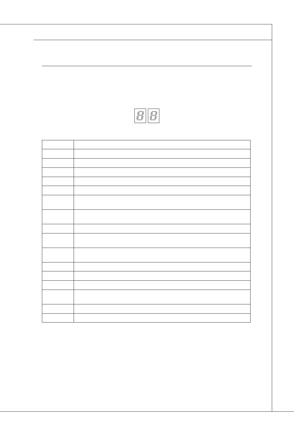
Led i
ndicator
Debug LED: LED1, LED2
Please refer to the table below to get more nformaton about the Debug LED
message.
Post
Status
FF
Power on and first initialize CPU.
C0, C1, C2
Early CPU Intalze.
C4, C6
Intalze chpset.
D4, D5
Intalze memory.
08
Intalze keyboard.
2A, 31
Intalze onboard devces. Load Opton ROM (VGA and RAID opton ROM) form BIOS
to memory.
37
Dsplayng sgn-on message, CPU nformaton, setup key message and any OEM spe-
cific information.
38
Intalze USB devce and dfferent devces.
3C
Md POST ntalzaton of chpset regsters. Detect dfferent devces (parallel ports, seral
ports and coprocessor n CPU...etc.)
75, 78
Intalze INT 13 devces and IPL devces. (nclude SATA/ PATA HDD and CD/DVD
ROM).
87
Enter setup screen. BIOS setup f needed/ requested.
A4
Wait for user input at configuration display if needed.
A7
Display the system configuration screen if enabled.
B1Save
Save system context for ACPI (Advanced Configuration and Power Interface).Prepare
gve control to OS loader (INT 19H).
00
Pass control to OS Loader (typcally INT 19H).
AA
Enter OS (Vsta or Wndows
®
XP).