Help menu, An introduction of aicm equipment, Confidential – KMW Communications AICM User Manual
Page 15
Sheet 15 of 17
Sheet 15 of 17 05-30-2006
CONFIDENTIAL
11. Help menu
A dialog box in Figure 11-2 appears when the user selects an About New Aicm menu (Figure 11-1). It has the
program version and other information.
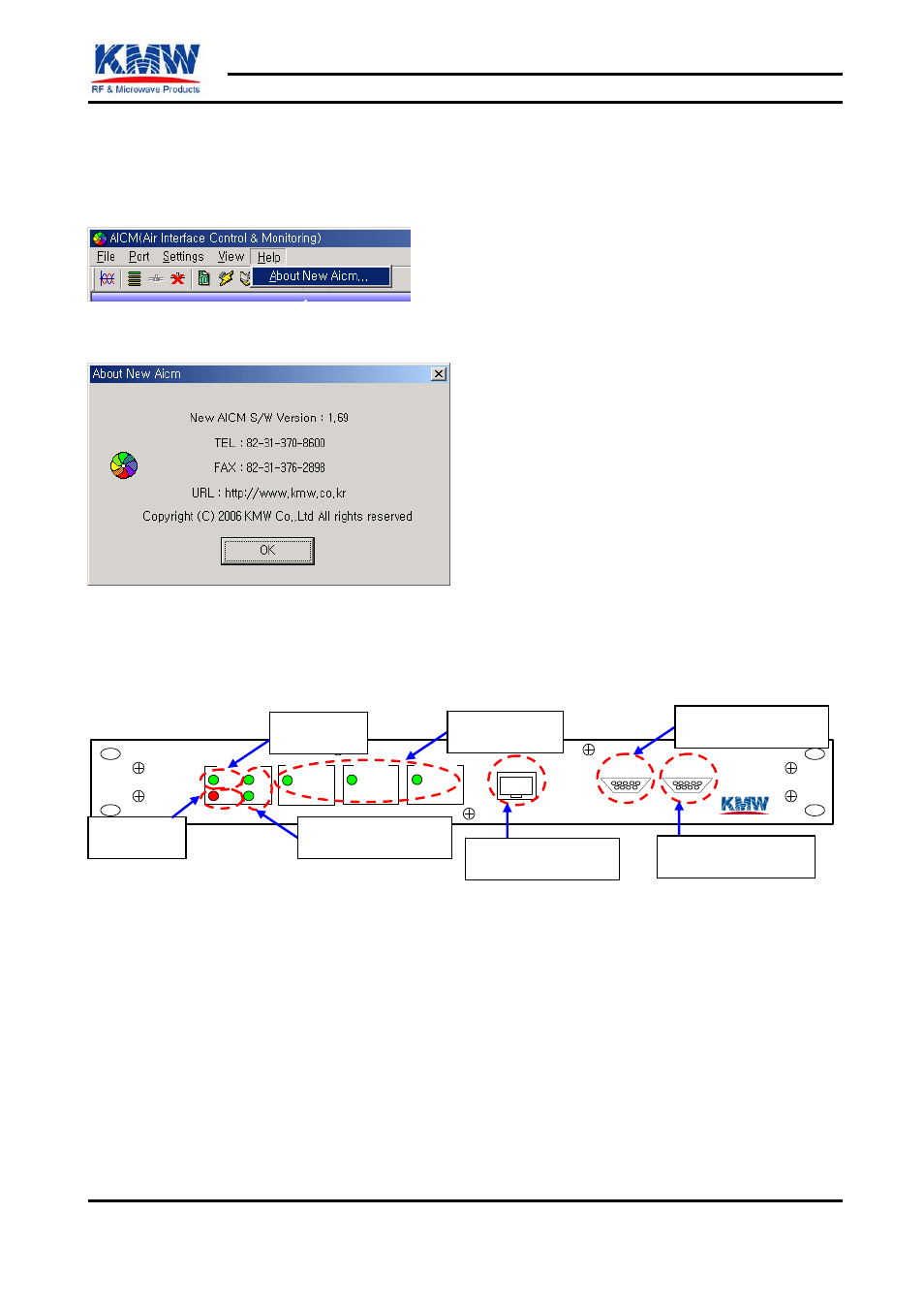
12. An introduction of AICM equipment
Figure 12-1 shows a front panel of AICM equipment and Figure 12-2 shows a rear panel.
AICM
PWR
ALM
TX
RX
STATUS
OPER
ALPHA
OPER
BETA
OPER
GAMMA
Ethernet
1
RS- 485/422
DEBUG
RS-485 COM. PORT
Power LED
DATA TX/RX LED
Operation LED
Alarm LED
RS-232 COM. PORT
TCP/IP COM. PORT
Power LED: A green LED turns on while a power supplies to AICM.
Alarm LED: A red LED turns on while any alarms are encountered.
DATA TX/RX LED: A green LED turns on while some data are transmitted and received by TCP/IP or RS-
232 communication.
Operation LED: A green LED turns on when an antenna for ALPHA, BETA, and GAMMA of each sector
is installed. The program manages the setting.
TCP/IP COM. PORT: This port is used for NMS Program. This is connected into the system network.
RS-485 COM. PORT: A RS-485 communication part. It will be used later.
RS-232 COM. PORT: This is used for managing a 1:1 interface program.
Copyright © 2006 KMW Inc., All Rights Reserved