Howard HI-102 Overhead Transformer User Manual
Page 27
Document 2.4.95, Revision 0
May, 2013
27
Fluid-Filled Overhead Distribution Transformers
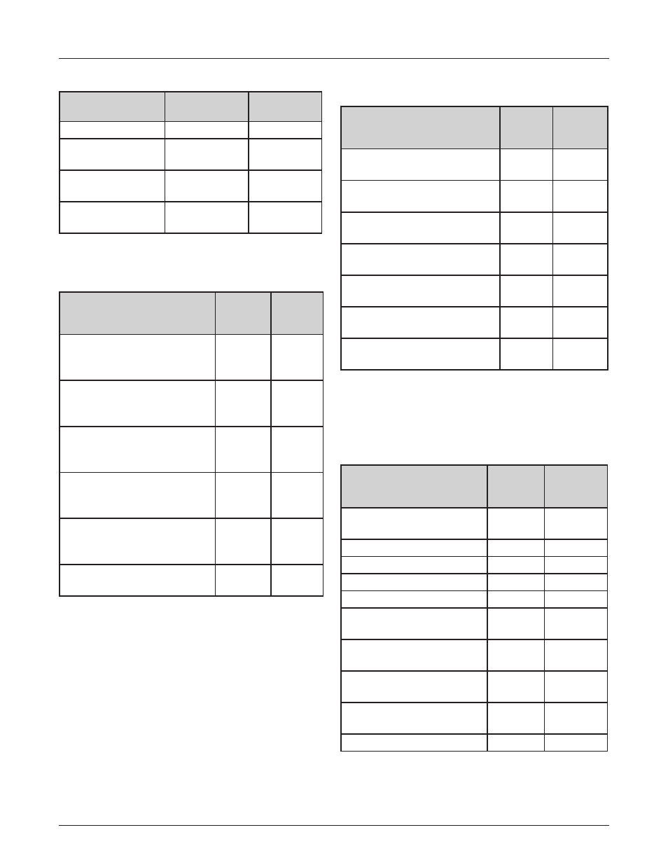
Table 1: Torque Guidelines for External Fasteners
Fastener Type
Nominal Torque
(in-lbs)
Torque Range
(in-lbs)
3/8” bolt
240
220-260
Hand-hole cover
bolt
144
129-158
Fastener Type
Cover band bolt
180
170-185
Surge arrester
mounting bolts
420
372-368
Table 2: Torque Guidelines for External Bushing
Mounting Hardware
Bushing Type
Nominal
Torque
(in-lbs)
Torque
Range
Low-voltage bushing, molded
Tri-Clamp (without clamp
ring), 3/8” mounting studs
60
40-80
Low-voltage bushing, molded
(with clamp ring), 3/8”
mounting studs
120
90-150
Low-voltage bushing, porce-
lain (with clamp ring), 1/2”
mounting studs
80
70-90
High-voltage bushing, mold-
ed Tri-Clamp (without clamp
ring), 3/8” mounting studs
60
40-80
High-voltage bushing,
molded (with clamp ring),
3/8” mounting studs
120
90-150
High-voltage bushing, porce-
lain
80
70-90
When checking tightness of gasketed components, the measured torque
will normally be less than the nominal torque listed in the table above due to
relaxation of the gasket material. Additional tightening of bushing mounting
hardware may cause the component to crack or the gasket to become over-
compressed.
Table 3: Torque Guidelines for External Terminal
Connections
Terminal Type
Nominal
Torque
(in-lbs)
Torque
Range
High-voltage porcelain bush-
ing eye-bolt
210
180-240
High-voltage porcelain bush-
ing end cap
168
156-180
Low-voltage bushing, 5/8”
jam nut
600
480-720
Low-voltage bushing, 1” jam
nut
600
480-720
Low-voltage bushing, 1-1/4”
jam nut
720
600-840
External surge arrester line
lead
180
162-198
External surge arrester
ground lead
180
162-198
When checking tightness of gasketed components, the measured torque
will normally be less than the nominal torque listed in the table above due to
relaxation of the gasket material. Additional tightening of bushing mounting
hardware may cause the component to crack or the gasket to become over-
compressed.
Table 4: Torque Guidelines for Accessories
Component
Nominal
Torque
(in-lbs)
Torque
Range
(in-lbs)
Bushing-mounted weak-
link fuse mounting bolts
85
80-90
Fluid-level sight plug
960
900-1020
Fill plug
960
900-1020
Drain plug
960
900-1020
Drain valve
600
480-720
Automatic pressure relief
device, 1/4” NPT
180
160-200
Automatic pressure relief
device, 1/2” NPT
360
324-396
Neutral strap fastener (at
ground pad)
160
140-180
Series/multiple, delta/wye
or tap switch mounting nut
120
96-144
Ground connector
160
140-180
When checking tightness of gasketed components, the measured torque
will normally be less than the nominal torque listed in the table above due to
relaxation of the gasket material. Additional tightening of bushing mounting
hardware may cause the component to crack or the gasket to become over-
compressed.