Cirrus Logic AN265 User Manual
Cirrus Logic Hardware
Copyright
© Cirrus Logic, Inc. 2005
(All Rights Reserved)
AN265
EP93xx RTC Oscillator Circuit
Note: This application note is applicable to all revisions of the EP93xx device.
1. BACKGROUND
Cirrus Logic has found that the Real Time Clock (RTC) circuit in the current EP93xx devices is susceptible
to on-chip noise, which can generate an inaccurate clock count and possibly cause the IC to boot into an
improper state during power-up.
To correct this issue, customers need to provide a clean square wave input to the RTCXTALI pin. This
may be accomplished several ways, such as by using an external clock oscillator or a dedicated RTC chip
like the DS1337. This application note, however, shows the use of an external Pierce oscillator circuit to
replace the existing internal RTC circuit.
Please note that an external RTC oscillator circuit is required for the EP93xx family on both existing and
future revision parts.
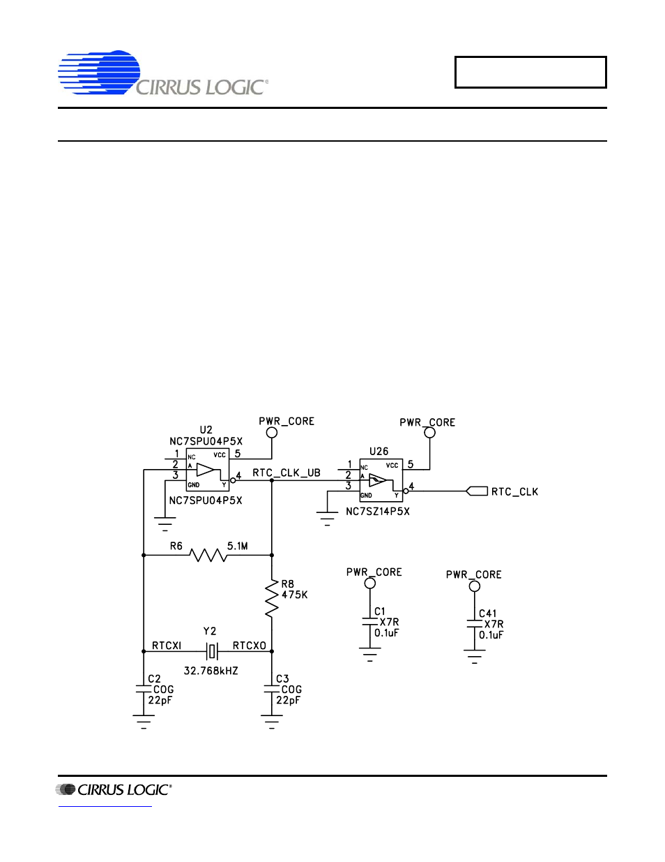
2. IMPLEMENTATION
Figure 1. Implementation Using a Pierce Oscillator Circuit and Schmitt-trigger Inverter
DEC ‘05
AN265REV2