4 rs-232 interface, 5 header interface, 4 rs-232 interface 1.5 header interface – Cirrus Logic CDB8130 User Manual
Page 5: Cdb8130
CDB8130
DS170DB5
5
allows systems using only one LED to operate with
a much higher drive current than can be sourced by
using a single driver. To connect the transmitter
drivers in this way, install jumper J17.
The LED transmitter driver resistors (R3 and R4)
are optimized for a power supply voltage of 3.3V.
For operation at voltages greater than this, the val-
ues of these resistors must be increased.
1.4
RS-232 Interface
The CDB8130 is designed to connect to any stan-
dard RS-232 port through the female DB-9 connec-
tor marked “RS-232.” The MAX562 (U2) supplies
the voltage level translation function, taking the ±
12V RS-232 levels and translating them to standard
CMOS logic levels.
Table 1 shows the default mapping of UART sig-
nals to CS8130 pins.
1.5
Header Interface
If desired, the RS-232 level translator can be re-
moved from the circuit. The signals are discon-
nected by removing jumpers J5, J6, J7, J8, and J9.
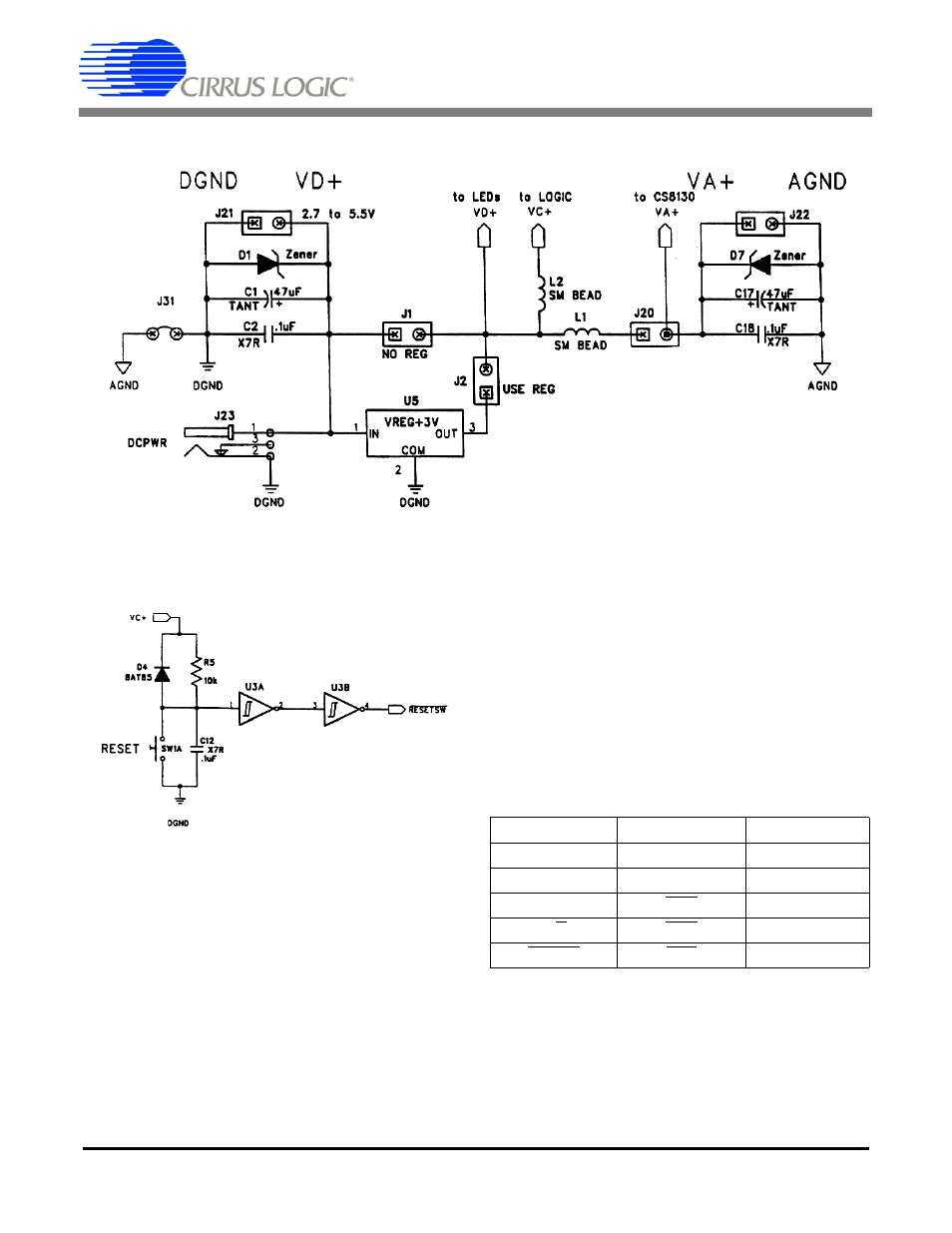
Figure 2. Power Supply Circuitry
Figure 3. Reset Circuit
CS8130 Pin
UART Signal
Direction
RXD
RXD
to UART
TXD
TXD
to CS8130
FORM/BSY
CTS
to UART
D/C
DTR
to CS8130
RESET
RTS
to CS8130
Table 1. CS8130-to-UART Connections