6 “vol_down” pushbutton, 7 “vol_up” pushbutton, Command serial port description – Cirrus Logic CDB6422 User Manual
Page 8: 1 command list, 6 “vol_down” pushbutton: 2.6.7 “vol_up” pushbutton, Cdb6422
CDB6422
8
DS295DB2
The KEYPAD and status LEDs return to their nor-
mal states after the Configuration number has been
selected.
Because the Configuration sets are stored in EE-
PROM, they will survive a power-off event. How-
ever, Configuration 0 is special for two reasons: 1)
it is reset to the CS6422 default register state on
power-up or on microcontroller reset, and 2) it is
automatically downloaded to the CS6422 when the
“6422_RST” pushbutton is pressed (or the 'r' com-
mand is sent from a terminal).
Thus, if you wish to test a RESET configuration
state and you will be testing the board from power-
off (for example, if you set up your configuration
registers in the lab and want to perform testing in a
car), you must store the configuration to be tested
in Configuration space (1..9). Once the board has
been powered for testing in the target environment
(the car), you can RECALL the saved configura-
tion and STORE it in Configuration 0. Pressing the
“6422_RST” button will reset the CS6422 and
download the Configuration 0 information to the
device for testing.
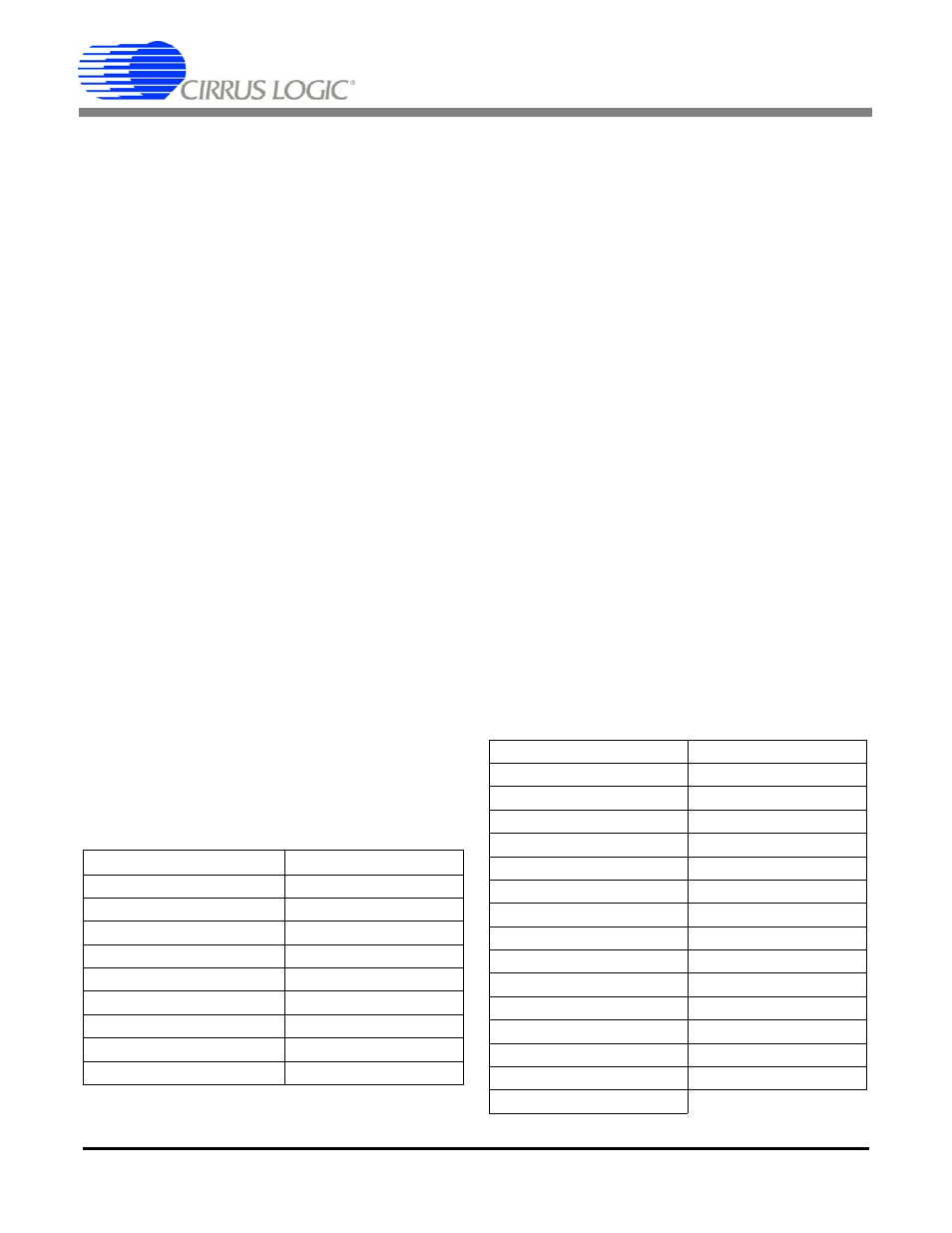
2.6.6
“VOL_DOWN” PUSHBUTTON:
Pressing the "VOL_DOWN" pushbutton decreases
the receive (speaker) volume by 3dB per button
press until RVol = 'mute'. The current receive vol-
ume is reflected in the status LED bar with the fol-
lowing mapping:
2.6.7
“VOL_UP” PUSHBUTTON:
Pressing the "VOL_UP" pushbutton increases the re-
ceive (speaker) volume by 3dB per button press until
RVol = '+30dB'. The receive volume is reflected in
the status LED bar with the mapping described in the
“VOL_DOWN” Pushbutton description.
3. COMMAND SERIAL PORT
DESCRIPTION
The CDB6422 can operate connected to a PC or in a
stand-alone configuration. If connected to a PC, the
board can be controlled by supplied Windows-based
software or through a simple terminal program. The
board communicates at 19.2kbps, 8 data bits, 1 stop
bit, and no parity or handshaking of any kind. All
commands and responses are standard ASCII text
with no special characters or binary data.
This section describes the commands and response
primitives that the board accepts and provides
through the serial connection. This can be thought
of as a "command list" for "terminal" mode.
3.1
Command List:
The following is a listing of commands and messag-
es that the CDB6422 (Rev. A) evaluation board ac-
cepts and transmits through the serial connection.
# LEDs on
RVol Value
0
mute
1
-12 to 0 dB
2
+3 to +6 dB
3
+9 to +12 dB
4
+15 to +18 dB (default)
5
+21 dB
6
+24 dB
7
+27 dB
8
+30 dB (maximum)
ver
reset
r
wr
wrb
rd
swd
swu
swp
off_hook
on_hook
d_reset
doff
dtmf
kd
ku
st
pd
pu
vol_up
vol_down
mute
unmute
save
recall
ring
mwr
uc
ext
d
?