An313, Minimizing emi – Cirrus Logic AN313 User Manual
Page 3
AN311REV1
3
AN313
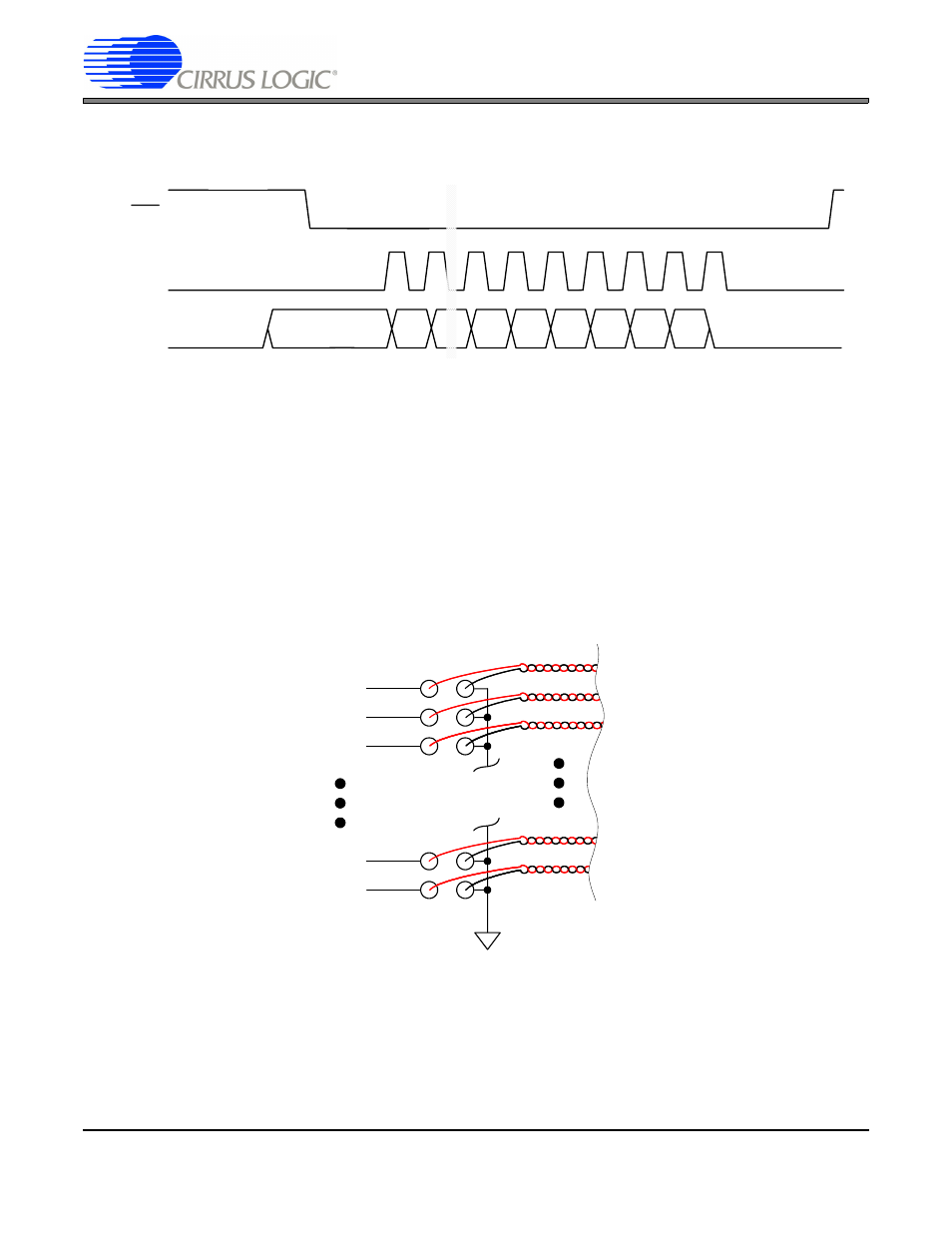
Figure 2 shows the timing of the RDY/, SCLK, and SDO signals from the A/D converter.
Figure 2. CS556x/7x/8x Serial Data Output Signals
4. Minimizing EMI
There are applications where output data from a converter must pass via a cable to another circuit board assembly.
If this is required, each active signal should have its own ground wire “partner”. On a connecter, such as a dual row
stake header, each active signal should be paired with a ground signal. Any connecting cable should be constructed
from twisted pair ribbon cable where each active signal has its own ground “partner” which is the other wire in the
twisted pair. This minimizes radiated noise and reduces the likelihood that radiated noise will interfere with converter
performance. It aslo enhances the likelihood that the system will pass any EMC (electromagnetic compatibility) re-
quirements.
This wiring method is illustrated in Figure 3.
Figure 3. Recommended Connector & Cable Configuration
RDY
SCLK(o)
SDO
MSB
MSB–1
LSB
LSB+1
D0
D23
D1
D21
D22