An311 – Cirrus Logic AN311 User Manual
Page 3
AN311REV1
3
AN311
If the FRS bit is set to logic 1, the converter can provide output word rates of 3200, 1600, 800, 400, 200, 100, 50,
25, 12.5, and 6.25 samples per second. When set to output word rates of 50, 25, 12.5, or 6.25 Sps, the filter will
provide zeroes in the transfer function that will yield excellent rejection of 50 Hz line interference components.
Therefore, the CS5530/31/32/33/34 series of A/D converters provide the user the option of setting the FRS bit in the
configuration register to modify the digital filter zero placement to be optimized for notching out either 50 Hz or
60 Hz.
4. The CS5530/31/32/33/34:
A Method to Place Filter Zeroes at 50 Hz & 60 Hz Simultaneously
Some instrument manufacturers sell the same product design into multiple markets, some where 50 Hz line frequen-
cy is the standard and others where 60 Hz line frequency is standard. The CS5530/31/32/33/34 providie the oper-
ator with a software-selectable option for setting the FRS bit for 50 Hz or for 60 Hz. However, it may be desirable
for the instrument to attenuate both 50 Hz and 60 Hz simulataneously.
There are several methods available to achieve both 50 Hz and 60 Hz attenuation. The method chosen depends
upon the level of rejection that is needed in the application. There are two possible options which can provide line
rejection of 50 Hz and 60 Hz that do not require the instrument user to make a software selection for line frequency.
The first solution is to operate the converter with the word rate set at 50 Sps and accept the amount of line rejection
that this filter selection provides at 60 Hz.
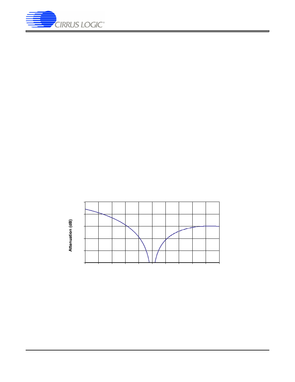
Figure 3 illustrates an expanded view of the Sinc
3
filter attenuation around the region of 0.5 to 1.5 times the output
word rate when the word rate is scaled to 1 on the plot. With the converter set to output words at 50 Sps, the graph
extends from 25 Hz to 75 Hz. Therefore, the graph actually illustrates the attenuation of the Sinc
3
filter across 25 Hz
to 75 Hz when the output word rate of the ADC is et for 50 Sps. One can read from the graph the amount of atten-
uation that would occur at any frequency from 25 Hz to 75 Hz when the word rate is set to 50 Sps.
Figure 3. Third-order Sinc Filter Response (Sinc
3
), Normalized to 1
This graph can be used to determine the attenuation of the filter if the line frequency varies from 50 Hz. The filter
notch frequency is determined by the clock source to the ADC and by the settings of the FRS bit and the word rate
selection. In some electric utilities, the line frequency may vary widely. If the nominal line frequency of 50 Hz varies
from 45 to 55 Hz the attenuation at these frequencies can be determined from the plot.
For example, for a line frequency of 45 Hz, one would examine the plot at 0.9 (45/50 = 0.9) and find that attenuation
for 45 Hz would be about 58 dB.
-100
-80
-60
-40
-20
0
0.5
0.6
0.7
0.8
0.9
1.0
1.1
1.2
1.3
1.4
1.5
25
30
35
40
45
50
55
60
65
70
75
Frequency (Hz)
Normalized
Actual Freq.