2 tdm format, Figure 12. tdm format, 3 configuring serial audio interface format – Cirrus Logic CS5366 User Manual
Page 23: Table 2. dif1 and dif0 pin settings, 6 speed modes, 1 sample rate ranges, 2 using m1 and m0 to set sampling parameters, Table 3. m1 and m0 settings, Cs5366, 6 speed modes 4.6.1 sample rate ranges
DS626F5
23
CS5366
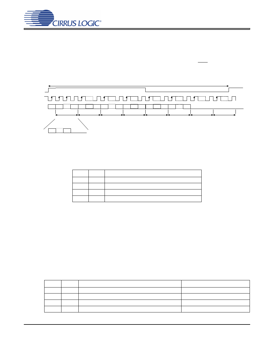
4.5.2 TDM Format
In TDM Mode, all six channels of audio data are serially clocked out during a single Frame Sync (FS) cycle,
as shown in
. The rising edge of FS signifies the start of a new TDM frame cycle. Each channel
slot occupies 32 SCLK cycles, with the data left justified and with MSB first. TDM output data should be
latched on the rising edge of SCLK within time specified under
”Serial Audio Interface - TDM Timing” sec-
. The TDM data output port resides on the SDOUT1 pin. The TDM output pin is compli-
mentary TDM data. All SDOUT pins will remain active during TDM Mode. Refer to
Performance in TDM Mode” on page 29
for critical system design information.
Figure 12. TDM Format
4.5.3 Configuring Serial Audio Interface Format
The serial audio interface format of the data is controlled by the configuration of the DIF1 and DIF0 pins in
Stand-Alone Mode or by the DIF[1] and DIF[0] bits in the Global Mode Control Register in Control Port
Mode, as shown in
Table 2. DIF1 and DIF0 Pin Settings
4.6
Speed Modes
4.6.1 Sample Rate Ranges
CS5366 supports sampling rates from 2 kHz to 21 kHz, divided into three ranges: 2 kHz - 54 kHz, 54 kHz -
108 kHz, and 108 kHz - 216 kHz. These sampling speed modes are called Single-Speed Mode (SSM),
Double-Speed Mode (DSM), and Quad-Speed Mode (QSM), respectively.
4.6.2 Using M1 and M0 to Set Sampling Parameters
The Master/Slave operation and the sample rate range are controlled through the settings of the M1 and
M0 pins in Stand-Alone Mode, or by the M[1] and M[0] bits in the Global Mode Control Register in Control
Port Mode, as shown in
Table 3. M1 and M0 Settings
DIF1
DIF0
Mode
0
0
Left-Justified
0
1
I²S
1
0
TDM
1
1
Reserved
M1
M0
Mode
Frequency Range
0
0
Single-Speed Master Mode (SSM)
2 kHz - 54 kHz
0
1
Double-Speed Master Mode (DSM)
54 kHz - 108 kHz
1
0
Quadruple-Speed Master Mode (QSM)
108 kHz - 216 kHz
1
1
Auto-Detected Speed Slave Mode
2 kHz - 216 kHz
Channel 6
SCLK
LSB
MSB
LSB
MSB
LSB
MSB
LSB
MSB
LSB
MSB
LSB
MSB
TDM OUT
Channel 1
Channel 4
Channel 2
Channel 5
Channel 3
32 clks
32 clks
32 clks
32 clks
32 clks
32 clks
32 clks
32 clks
FS
LSB
LSB
MSB
Data
Zeroes