Applications, 1 digital connections, 2 analog connections – Cirrus Logic CS4461 User Manual
Page 8: Figure 2. cs4461 recommended analog input buffer, 1 digital connections 4.2 analog connections
8
DS650F1
CS4461
4. APPLICATIONS
4.1
Digital Connections
PSR_MCLK provides the system clock for the CS4461. PSR_SYNC and PSR_DATA provide the output of
the modulator to the class-D modulator with feedback capabilities. Series damping resistors should be used
on PSR_MCLK, PSR_SYNC, and PSR_DATA to minimize noise. These should be placed as close as pos-
sible to their signal source. The pin labeled TEST should also be pulled low to GND through a 47 k
Ω resistor
to minimize noise coupling into the ADC modulator.
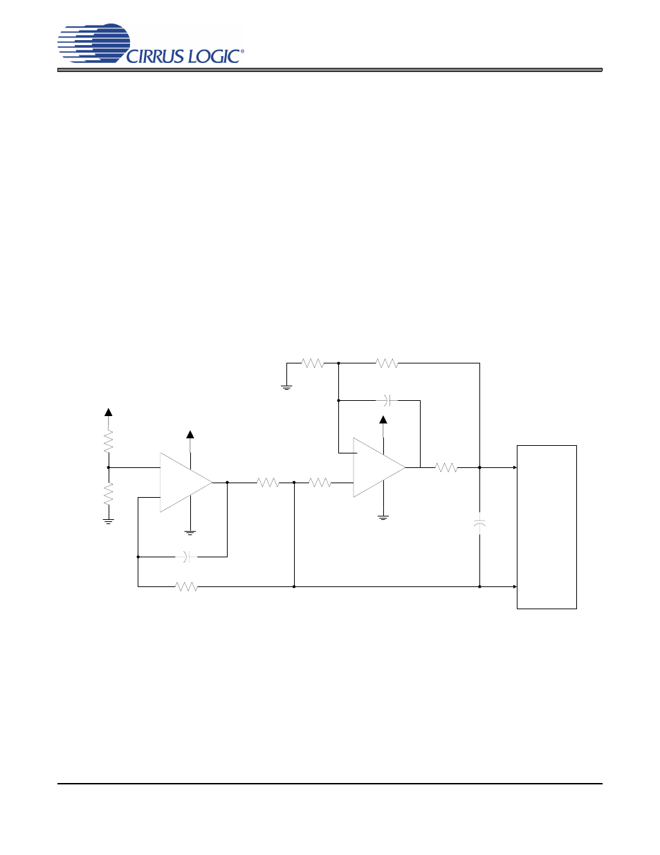
4.2
Analog Connections
The analog modulator samples the input at PSR_MCLK/4 (6.144 MHz with PSR_MCLK=24.576 MHz).
shows the suggested analog input filter. This filter topology will correctly buffer the power supply’s
AC and DC components for PSR processing by the class-D modulator. The use of capacitors which have a
large voltage coefficient (such as general purpose ceramics) must be avoided since these can degrade sig-
nal linearity. C0G dielectrics should be used wherever possible. R1 and R2 should be used to scale VP
(class-D amplifier high voltage power supply) to less than the CS4461 maximum AIN+/AIN- input voltage
(3.9 V).
The following equation can be used to scale R1 and R2:
2 * (VP * (1 + %
VP_Ripple
)) * (R2 / (R1 + R2)) < 3.9 V
Example (VP = 40 V, %
VP_Ripple
= 4%):
2 * (40 * (1 + 0.04)) * (1.96 k
Ω / (40.2 kΩ + 1.96 kΩ) = 3.87 V
CS4461
AIN+
AIN-
2200 pF
C0G
-
+
90.9
Ω
120 pF
2 k
Ω
2 k
Ω
+5.0 V
649
Ω
90.9
Ω
+
-
+5.0 V
120 pF
649
Ω
VP
R1
R2
Figure 2. CS4461 Recommended Analog Input Buffer